Multi-speed transmission and integrated drive transfer mechanism

a transmission mechanism and multi-speed technology, applied in the direction of mechanical actuated clutches, interengaging clutches, gearing, etc., can solve the problems of inability insufficient current transmission cases for good shift quality, and inability to adjust the gear ratio, etc., to achieve good transmission quality and robust park system function.

Inactive Publication Date: 2005-10-18
FORD GLOBAL TECH LLC
View PDF15 Cites 179 Cited by
  • Summary
  • Abstract
  • Description
  • Claims
  • Application Information

AI Technical Summary

Benefits of technology

[0008]A vehicle driveline having a transmission that produces eight to ten speed ratios in combination with a single speed transfer case according to the present invention is used to provide the extended speed ratio range needed to meet the diverse requirements of a various vehicle lines, and the ability to shift from the low range to high range under full torque. The combination ensures good shift quality and robust park system function.
[0010]A coupler, such as a synchronizer is used to change between forward drive and reverse drive. The synchronizer improves fuel efficiency by eliminating two high-capacity, hydraulic friction clutches and their associated drag losses.

Problems solved by technology

Automatic shifting under full torque from the low speed range to high speed range is a goal in driveline design, but the speed ratio step, from the low range to high range, in current transfer cases is too large for good shift quality and would need to be reduced to approximately 1.8 or less.
However, performance degradation due to the resulting lower gear ratios would be undesirable.
The use of multi-plate clutches in the transfer case to shift from low to high, coupled with six-speed automatic transmissions would result in added parasitic drag and lower fuel economy.
But this would compound the losses.

Method used


Image

  • Multi-speed transmission and integrated drive transfer mechanism
  • Multi-speed transmission and integrated drive transfer mechanism
  • Multi-speed transmission and integrated drive transfer mechanism

Examples


Embodiment Construction

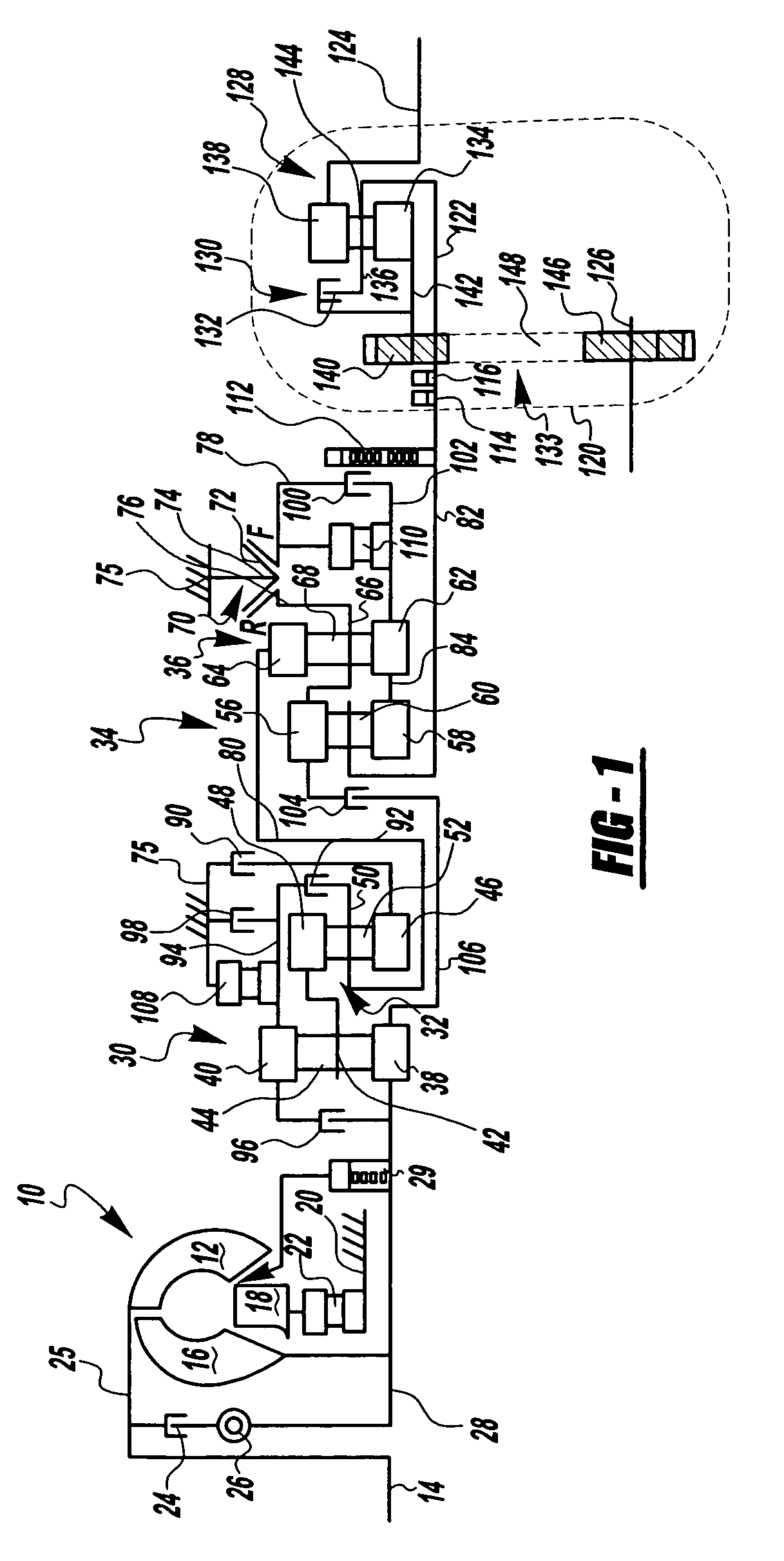
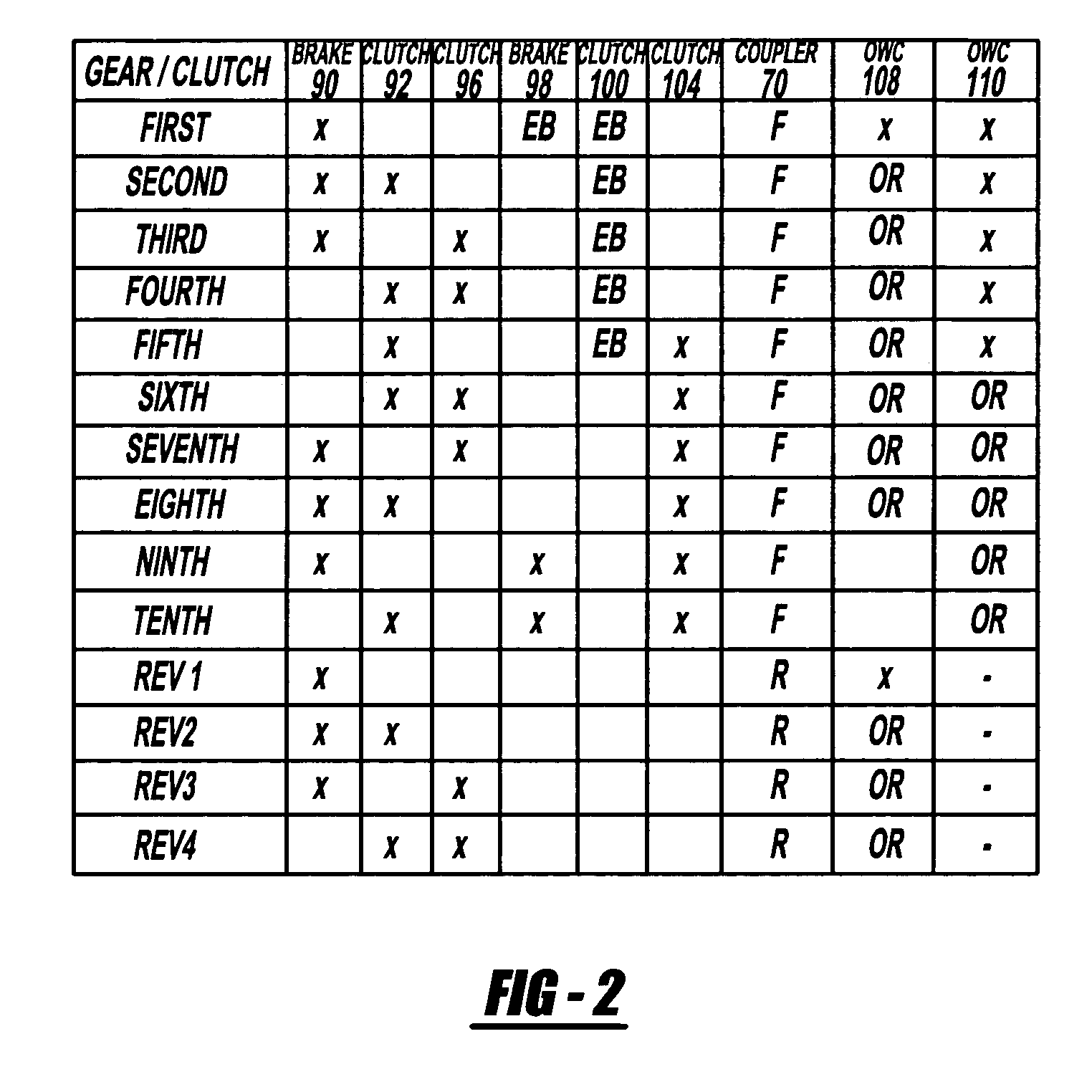
[0019]FIG. 1 shows a schematic diagram of a kinematic arrangement according to the present invention capable of producing ten forward speed ratios—five underdrive gear ratios, one direct drive ratio, and four overdrive ratios—and four reverse drive speed ratios. FIG. 2 shows the states of engagement and disengagement of various clutches and brakes corresponding to each speed ratio. The transmission arrangement of FIG. 1 includes four planetary gear sets, six multi-plate clutches and brakes that control the gearset elements, and a synchronizer for producing forward drive and reverse drive.

[0020]A hydrokinetic torque converter 10 includes an impeller 12 connected to the crankshaft 14 of an internal combustion engine, a bladed turbine 16, and a bladed stator 18. The impeller and turbine wheels define a toroidal fluid flow circuit, whereby the impeller is hydrokinetically connected to the turbine. The stator 18 is supported rotatably on a stationary stator sleeve shaft 20, and an overru...


PUM


Abstract

A multiple speed transmission capable of producing five underdrive gear ratios, one direct drive ratio, four overdrive ratios, and four reverse ratios includes four interconnected planetary gearsets, multi-plate clutches and brakes controlling the gearset elements, and a coupler that changes between forward drive and reverse drive by holding and releasing alternate gearset components against rotation on the transmission case. The transmission in combination with a single-speed transfer case having either an on-demand transfer clutch, or a full-time all-wheel drive system, are formed in an integrated package.

Description

BACKGROUND OF THE INVENTION[0001]1. Field of the Invention[0002]This invention relates to geared, automatic power transmissions for motor vehicles. More particularly, it pertains to the kinematic arrangement for such transmissions and a driveline that incorporates them.[0003]2. Description of the Prior Art[0004]A transfer case contains a drive mechanism for connecting an engine to the vehicle's wheels, a primary wheel set that is connected continually to the engine, and a secondary wheel set that is connected selectively to the engine through the transfer case. A two-speed transfer case produces both a high range and a low range of speed ratios. Each of the speed ratios produced by the transmission is operative in each of the drive ranges produced by the transfer case; therefore, the transmission-transfer case can produce in combination a multiple of the transmission gear ratios. In this way the transfer case provides greater functional flexibility to the vehicle operator, who has a...

Claims


Application Information

Patent Timeline
Patent Type & Authority Patents(United States)
IPC IPC(8): B60K17/34F16H3/44F16H3/66
CPCF16H3/66F16H2200/0056F16H2200/0069F16H2200/0091F16H2200/2012F16H2200/2048F16H2200/2053F16H2200/2064F16H3/44
Inventor THOMAS, STEVENHAMMOND, MATTHEW
Owner FORD GLOBAL TECH LLC
Why Eureka
Try Eureka