
Simple suspension bridge type belt conveyor

a belt conveyor and suspension bridge technology, applied in the direction of conveyor parts, rollers, transportation and packaging, etc., can solve the problems of short pillar spacing, difficult to implement in difficult terrain or cross existing building structures, and achieve the effects of reducing manufacturing costs, improving transportation efficiency, and increasing structure weigh

Inactive Publication Date: 2014-09-25
CABLE BRIDGE CONVEYOR
View PDF15 Cites 3 Cited by
  • Summary
  • Abstract
  • Description
  • Claims
  • Application Information

AI Technical Summary

Benefits of technology

The present invention provides a simple suspension bridge type belt conveyor that can smoothly pass through pillars of the conveyor belt, which results in higher conveying efficiency and lower manufacturing cost. The conveyor can be installed on the suspension bridge without the need for large pillars and can also overcome issues related to the curve of the bridge body. The invention allows for a more efficient and cost-effective conveyor system.

Problems solved by technology

The traditional support method has drawbacks like high cost, short pillar spacing, and difficult to implement in difficult terrain or crossing existing building structures.
However, the suspension bridge and the cable-stayed bridge need huge pillars which tower above the bridge body significantly.
With the steel ropes or steel cables suspended from the top of pillars, and the bridge body suspended underneath the steel ropes or steel cables, the cost is high.
This characteristic makes a conveyor unsuitable to be mounted on the simple suspension bridge directly.

Method used


Image

  • Simple suspension bridge type belt conveyor
  • Simple suspension bridge type belt conveyor
  • Simple suspension bridge type belt conveyor

Examples


Embodiment Construction

[0025]Hereinafter, preferred embodiments of the present invention will be introduced in details, in order to help a person skilled in the art easily understand the advantages and characteristics of the present invention.

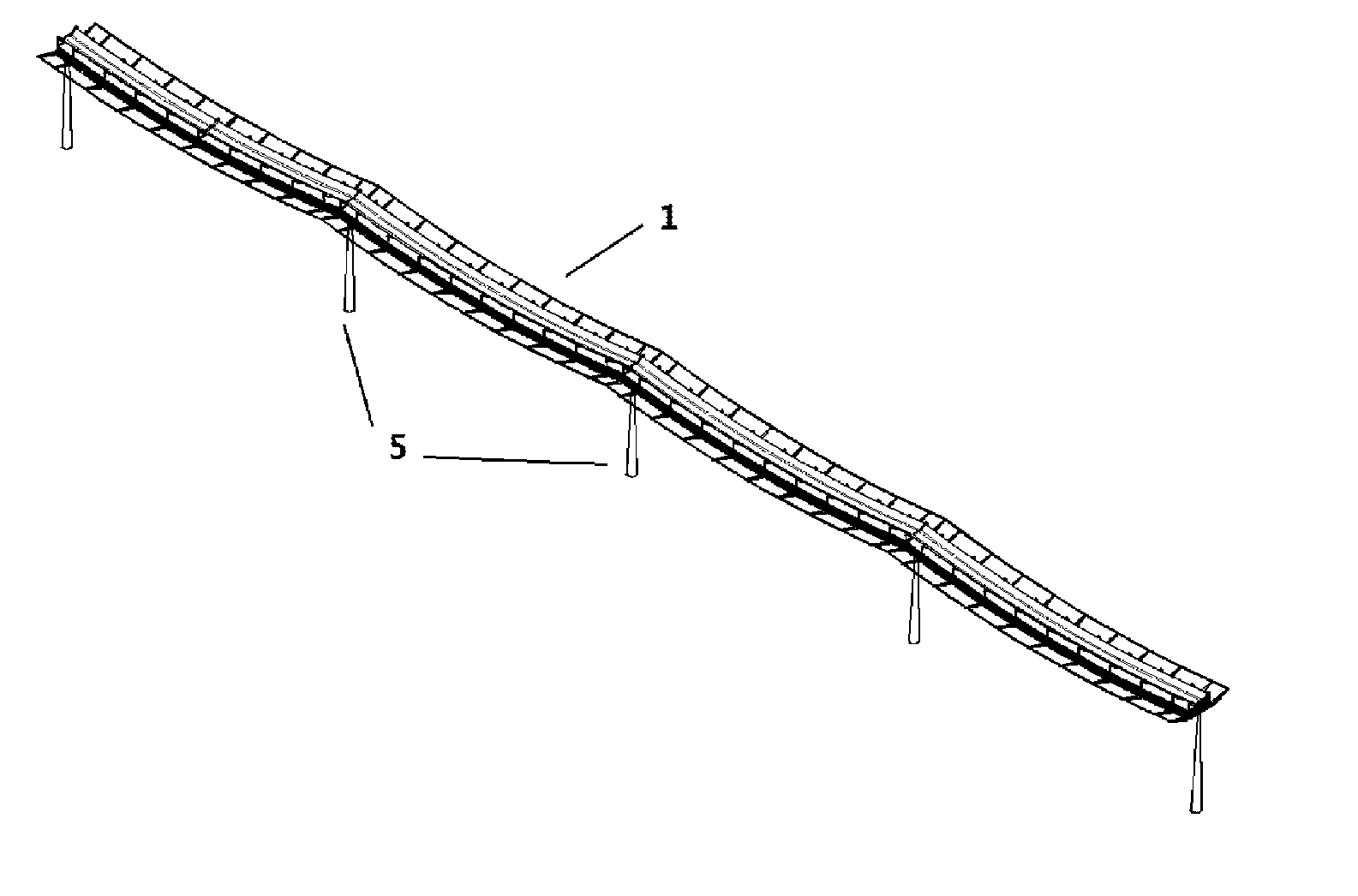
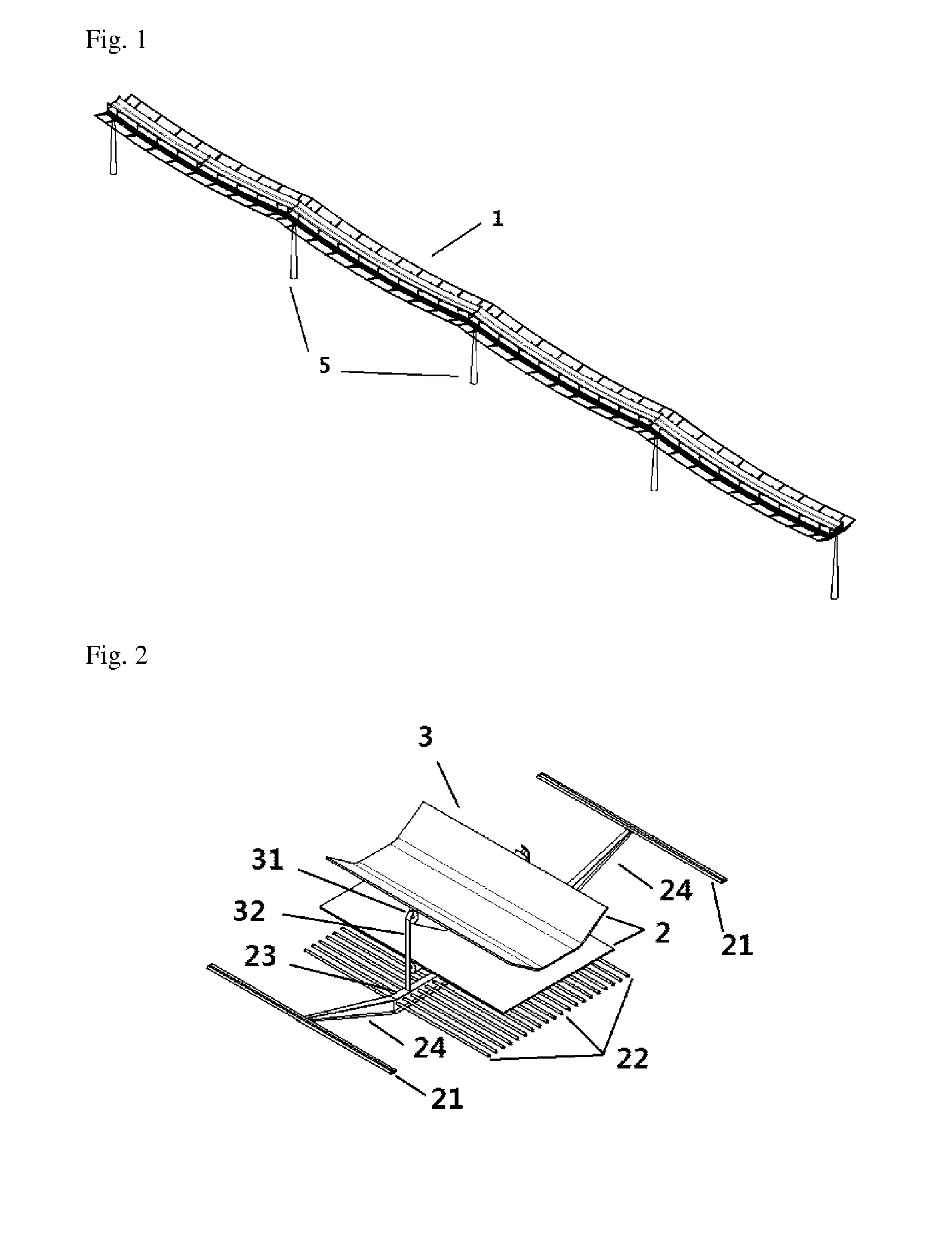
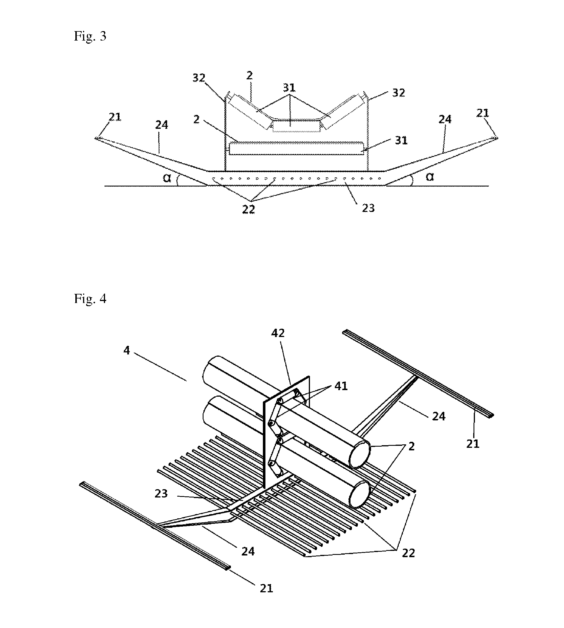
[0026]As FIGS. 1, 2, 3, 4 and 5 show, an embodiment of the present invention includes a simple suspension bridge type belt conveyor which comprises a simple suspension bridge body 1, a conveyor belt 2, a trough support rollers apparatus 3, a circular support roller apparatus 4. The floor of the simple suspension bridge body 1 is provided with a plurality of pillars 5. The trough support rollers apparatus 3 and the circular support roller apparatus 4 are fixed on upper end of the bridge body 1. The conveyor belt 2 conveys materials through the trough support rollers apparatus 3 and the circular support roller apparatus 4. The bridge body 1 comprises a cross beam 23, a plurality of bridge body steel cables 22 that are located at the center of the bridge, and edge steel...


PUM


Abstract

A simple suspension bridge type belt conveyor comprises a simple suspension bridge body (1), a conveyor belt (2), a trough support roller apparatus (3) and a circular support roller apparatus (4). A plurality of supporting pillars (5) are arranged beneath the simple suspension bridge body (1); the trough support roller apparatus (3) and the circular support roller apparatus (4) are fixed on the simple suspension bridge body (1). The conveyor conveys materials on the conveyor belt (2) which is moving through the trough support roller apparatus (3) and the circular support roller apparatus (4). The simple suspension bridge type belt conveyor enables the conveyor belt (2) to pass over the pillars (5) of simple suspension bridge without overstressing the conveyor belt (2), and has lower manufacturing cost and higher conveying efficiency.

Description

TECHNICAL FIELD[0001]The present invention relates to technical fields with respect to bridges and material handling and in particular, relates to a simple suspension bridge belt conveyor.BACKGROUND[0002]The simple suspension bridge is a kind of suspension bridge where the bridge body is hung from steel cables or steel wireropes that are supported on pillars separated by a certain distance. The belt conveyor is a conveying machine of which a continuously cycling endless conveyor belt for carrying materials is supported by carry rollers separated by a certain distance. The belt conveyor is also called as the conveyor (hereinafter, simply called as conveyor), and applied to fields such as mining, ports, factories and other areas where material handling is needed. The conveyor has advantages like lower cost, less environmental impact and higher energy efficiency, comparing to material handling by motor vehicles.[0003]The conveyor can be placed on the ground or elevated above the ground...

Claims


Application Information

Patent Timeline
Patent Type & Authority Applications(United States)
IPC IPC(8): B65G15/60
CPCB65G15/60B65G21/00B65G39/10B65G15/08
Inventor ZHANG, ZHILIN
Owner CABLE BRIDGE CONVEYOR
Learn More