Bearing implementation for a rotating electrical device

a technology of rotating electrical devices and bearings, which is applied in the direction of bearing units, mechanical energy handling, mechanical apparatus, etc., can solve the problems of direct financial loss to the end user in a production or critical uptime environment, failure of rear bearings, and general motor efficiency drop, so as to reduce or eliminate the cost of downtime and reduce the effect of cos

Inactive Publication Date: 2014-09-25
FXQ ENG GRP
View PDF4 Cites 1 Cited by
  • Summary
  • Abstract
  • Description
  • Claims
  • Application Information

AI Technical Summary

Benefits of technology

[0009]Advantageously, an electric motor including the at least three bearings may meet desired efficiency standards, e.g., minimum governmental efficiency standards, and continue to operate despite degradation or failure of a bearing. Moreover, an electric motor including at least three bearings may be more environmentally sustainable preventing damage to rotor and stator laminations, may reduce or eliminate the need for mid-shift shutdowns to replace failed motors, and may reduce costs associated with down time.

Problems solved by technology

However, as ball diameter is increased, the efficiency of the motor generally will drop as a result of increased friction losses resulting from increased surface area contact arising from the larger ball diameter.
Bearing degradation and failure is often cited as one of the main causes of failure in electric motors.
Due to the nature of electric motors, when a failure occurs, it typically happens on the front bearing.
The front bearing generally handles the majority of the load incident upon the motor, and therefore generally fails before the rear bearing.
When the front bearing fails, the entire motor will come to a stop resulting in unscheduled downtime, causing a direct financial loss to the end user in a production or critical uptime environment.
Further, in some cases, the laminations in the rotor and stator will be damaged due to their collision after degradation of the front bearing.
Thus, the end user often suffers financial costs associated with repairing or replacing the motor, and other costs associated with the down time of the motor.

Method used


Image

  • Bearing implementation for a rotating electrical device
  • Bearing implementation for a rotating electrical device
  • Bearing implementation for a rotating electrical device

Examples


Embodiment Construction

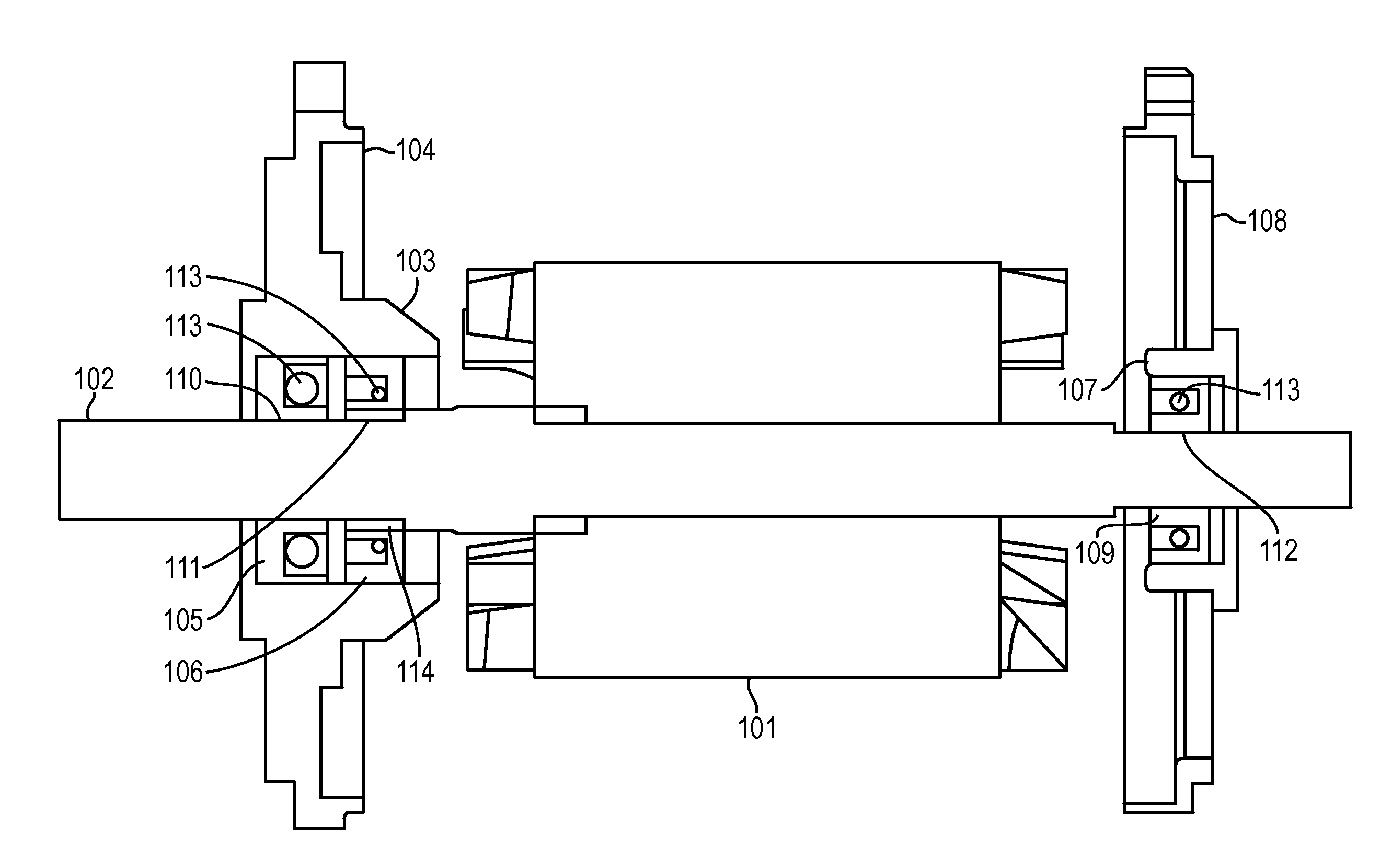
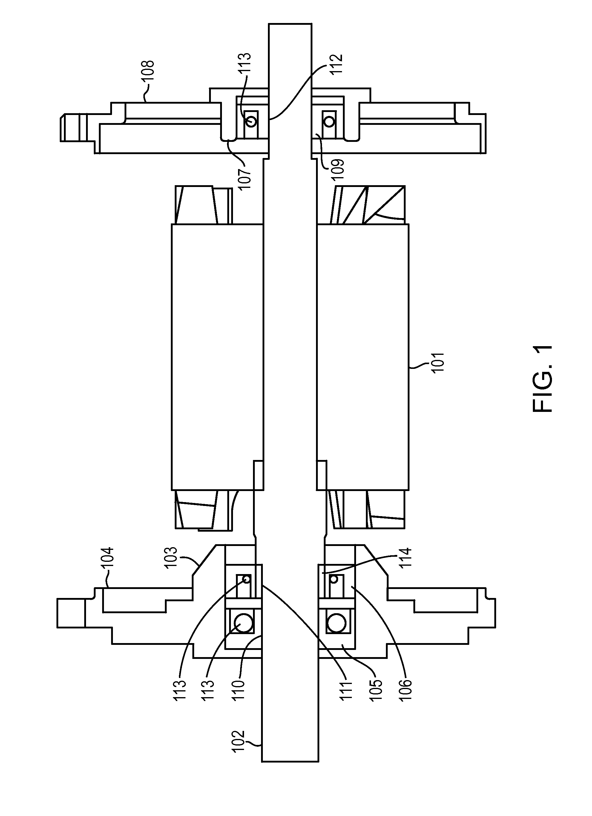
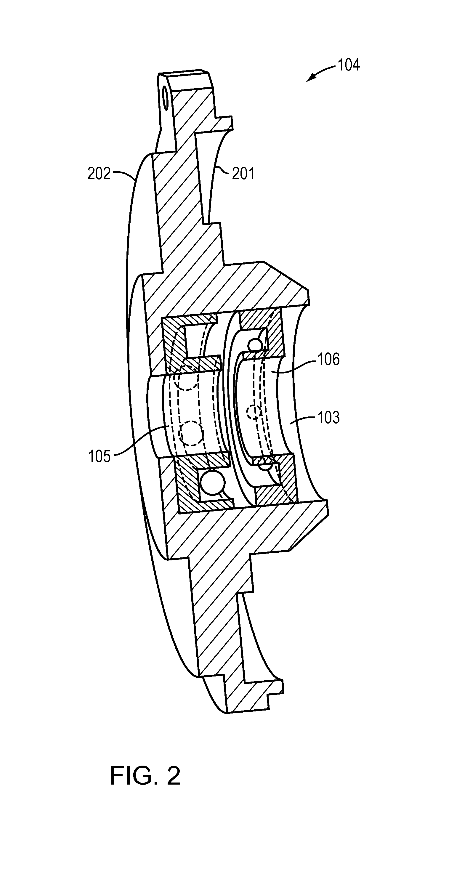
[0015]FIG. 1 depicts a cross section view of an example motor that includes at least three bearings. The motor 100 includes a rotor 101 that is pressed onto a shaft 102. Further, the motor 100 includes a housing 103 of a front plate 104, wherein the housing 103 maintains or holds two or more front bearings, for example, a front-most bearing 105 that is located furthest towards a proximal end of the shaft 102 and a backup or second bearing 106 that is located behind the front-most bearing 105, and is designed to handle the load for the front-most bearing 105 when the front-most bearing 105 degrades to a certain point or fails. In some instances, the front plate 104 may have to be modified to accommodate the two or more front bearings 105 and 106 or to meet desired performance and / or structural requirements. The two or more front bearings 105 and 106 may be embodied as individual and separate bearings within the housing 103, or the front-most bearings 105 and backup or second 106 may ...


PUM


Abstract

In one embodiment, an electric motor includes at least three bearings. The ball bearing utilized in the three bearings may be sized based on benchmark surface areas associated with the ball bearing utilized in a conventional electric motor having two bearings. Moreover, a technique may be implemented to reduce the diameter at a point on the shaft where a backup or second bearing makes contact with the shaft. When the motor begins to operate, for example, at a first time, the at least three bearings together handle a the load coming through the motor. When the front-most bearing degrades to a predetermined point or fails, for example, at a second time, the load transitions from the front most bearing to the second or backup bearing in the front plate.

Description

RELATED APPLICATIONS[0001]The present application claims priority to U.S. Provisional Patent Application No. 61 / 803,703, filed on Mar. 20, 2013 by Filipe Goncalves for a “Bearing Implementation Method for Rotating Electrical Equipment”, the contents of which are incorporated by reference herein in their entirety.BACKGROUND[0002]1. Technical Field[0003]The present application relates to a bearing implementation for a rotating electrical device, and more specifically to a bearing implementation for an electric motor having at least three bearings.[0004]2. Background Information[0005]Electric motors are typically mounted with a front and a rear bearing with the is intended purpose of providing a stable rotating environment for the rotor, thus turning electrical power into mechanical power. These bearings typically are rolling-element bearings that carry load by placing rolling elements (e.g., bearing balls) between two bearing rings. To maximize efficiency and to minimize losses due to...

Claims


Application Information

Patent Timeline
Patent Type & Authority Applications(United States)
IPC IPC(8): H02K7/08F16C35/06F16C41/00
CPCH02K7/083F16C41/004F16C35/061F16C19/52F16C19/56F16C2380/26B44D3/00B44D3/123H02K5/173
Inventor GONCALVES, FILIPEKIM, CHONG KYU
Owner FXQ ENG GRP
Why Eureka
Try Eureka