Wireless power transmission system, furniture having wireless charging function used therein, and wireless power transmssion apparatus used therein

a wireless charging and wireless technology, applied in the direction of circuit monitoring/indication, transportation and packaging, and the arrangement of several simultaneous batteries, etc., can solve the problems of instantaneous discharging phenomenon, fire or the like, and the battery pack lifespan may be reduced

Active Publication Date: 2014-09-25
GE HYBRID TECH
View PDF2 Cites 35 Cited by
  • Summary
  • Abstract
  • Description
  • Claims
  • Application Information

AI Technical Summary

Benefits of technology

[0017]The plurality of transmission coil units may be installed in parallel with each other on the upper surface of the flat plate, and the central transmission controlling unit may be installed on a lower surface of the center of the flat plate, and may include: an object sensor unit which senses a variation in one of a current and a voltage in the plurality of transmission coil units to generate an object sensing signal; a switching controller which turns on and off supplying of a power to the transmission coil unit; and a transmission controller which selects a transmission coil unit where the wireless power reception apparatus is positioned, based on the object se...

Problems solved by technology

However, when power is supplied using the terminal supplying scheme, as the charger contacts the battery pack or is separated from the battery pack, a terminal of the charger and a terminal of the battery pack may have different potential differences, which may cause an instantaneous discharging phenomenon.
Importantly, when foreign materials have accumulated on these terminals, there is a risk that a fire or the like will occur due to the instantaneous discharging phenomenon.
In addition, the electric energy charged in the battery pack is naturally discharged to the outside envi...

Method used


Image

  • Wireless power transmission system, furniture having wireless charging function used therein, and wireless power transmssion apparatus used therein
  • Wireless power transmission system, furniture having wireless charging function used therein, and wireless power transmssion apparatus used therein
  • Wireless power transmission system, furniture having wireless charging function used therein, and wireless power transmssion apparatus used therein

Examples


Embodiment Construction

[0036]Reference will now be made in detail to the present embodiments of the present invention, examples of which are illustrated in the accompanying drawings, wherein like reference numerals refer to the like elements throughout. The embodiments are described below in order to explain the present invention by referring to the figures.

[0037]In the following description, the terms “module”, “part”, and “unit” are used only for convenience. These terms do not have meanings or roles that distinguish components from each other or generally.

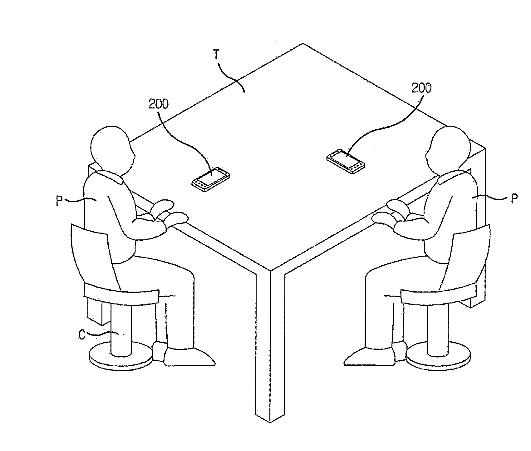
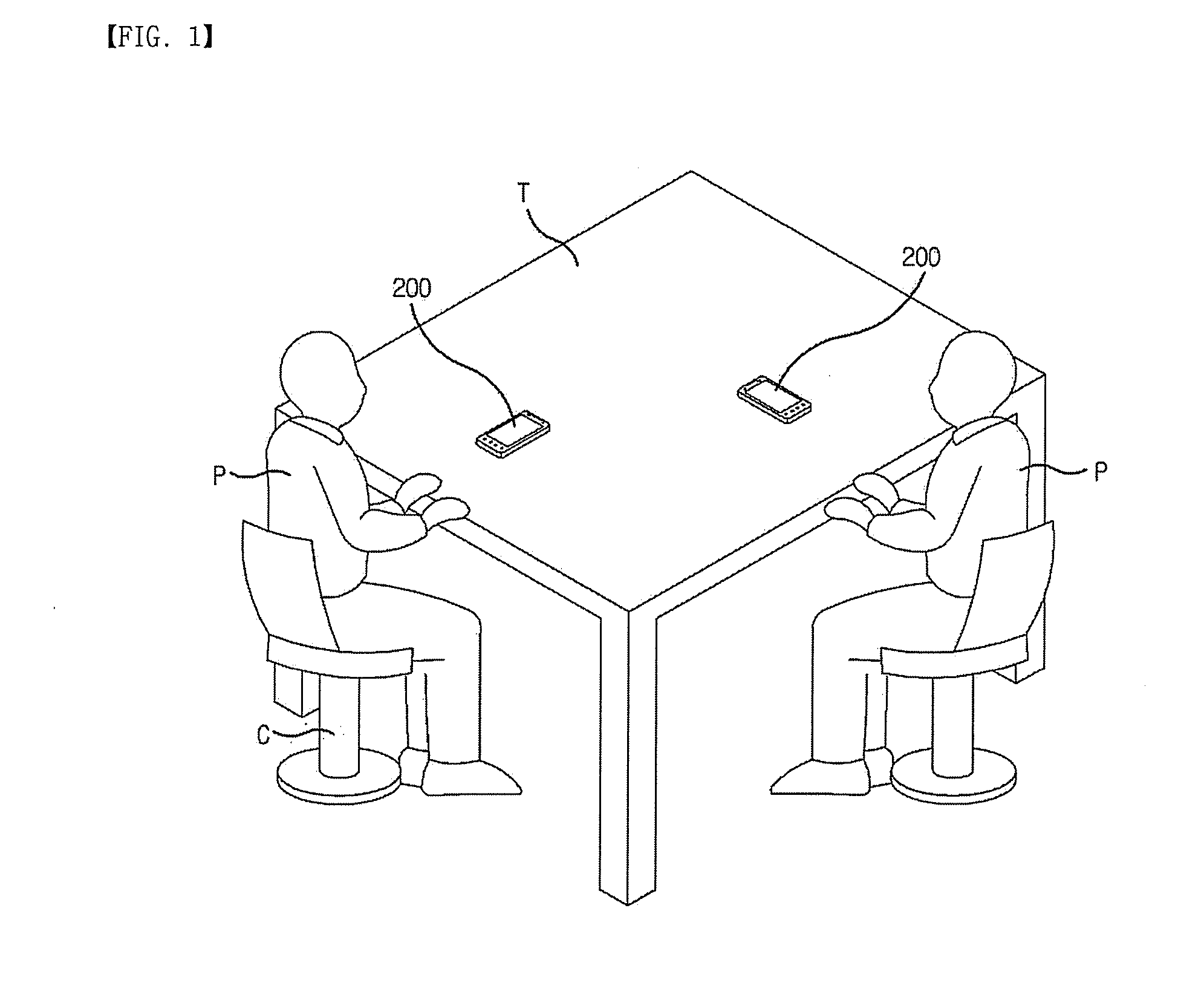
[0038]Hereinafter, a dining table is shown as a typical example of a furniture having a wireless charging function (i.e. a wireless power transmission apparatus). It is to be understood that the present invention is not limited thereto, but may be applied to any furniture having a flat surface where one or more electronic devices may be placed, including but not limited to an office table, a dresser, a desk, a shelf, or the like.

[0039]Likewise, a smar...


PUM


Abstract

Disclosed herein is a furniture having a wireless charging function, including: one or more transmission coil units disposed on the same plane of a flat plate of the furniture; and a central transmission controlling unit configured to select at least one transmission coil unit corresponding to a wireless power reception apparatus when the wireless power reception apparatus is placed on the flat plate, and to transmit a wireless power signal through the selected transmission coil unit, the central transmission controlling unit being installed separately from the plurality of transmission coil units.

Description

CROSS-REFERENCE TO RELATED APPLICATIONS[0001]This application claims the benefit of Korean Patent Application No. 10-2013-0029346, filed on Mar. 19, 2013, in the Korean Intellectual Property Office. All disclosures of the document named above are incorporated herein by reference.BACKGROUND OF THE INVENTION[0002]1. Field of the Invention[0003]The present invention relates to a wireless power transmission system, a furniture having a wireless charging function used therein, and a wireless power transmission apparatus used therein capable of conveniently charging a portable electronic device such as a smart phone, or the like.[0004]2. Description of the Related Art[0005]Generally, a battery pack supplies an operation power to a portable electronic device (such as a cellular phone, personal digital assistant, or the like). The battery pack is charged by receiving a power (such as electric energy) from an external charger, and is configured to include a battery cell in which the electric...

Claims


Application Information

Patent Timeline
IPC IPC(8): H02J7/02H02J7/00
CPCH02J7/025H02J50/12H02J50/402H02J7/0013H02J50/80H02J7/0048H02J50/90H02J7/0042H02J50/005H02J50/40H02J7/0047H02J7/0019
Inventor JUNG, CHUN-KIL
Owner GE HYBRID TECH
Why Eureka
Try Eureka