
Method for Integrating Virtual Object into Vehicle Displays

a technology for vehicle displays and virtual objects, applied in static indicating devices, navigation instruments, instruments, etc., can solve the problems of inability to wirelessly integrate virtual inability to reproduce the image of a display device correctly, and inability to wirelessly integrate virtual 3d objects with the correct overlap level, etc., to achieve the effect of improving reliability and robustness against method errors

Inactive Publication Date: 2014-09-25
DAIMLER AG
View PDF2 Cites 28 Cited by
  • Summary
  • Abstract
  • Description
  • Claims
  • Application Information

AI Technical Summary

Benefits of technology

The invention relates to a method for generating a virtual course of a road on a defined real 3D object space by synchronizing a virtual environmental model with camera position and navigation data. This method can ensure accurate and reliable generation of the virtual course of the road, even when there are poor visibility or recording conditions. Furthermore, the method can display the virtual 3D object on a front view display without adding excess information that may clash with the driver's view. This approach improves the reliability and accuracy of the virtual course of the road. Combining detected edge information with depth information can also enhance the accuracy of the virtual road model, without the need for further extraction or recalibration of camera position and configuration.

Problems solved by technology

However, a wireless integration of virtual objects with the correct level of overlap is not possible with image synthesis based solely on 2D information.
On the one hand, the perspective of the overlays often does not match the perspective of the camera image and, on the other hand, overlaid virtual objects permanently overlap the depiction of the back-ground of the camera images, even if real objects are closer than the overlays.
In other words, real and virtual objects are not superimposed correctly on the reproduced image of a display device.
As has already been mentioned, a wireless integration of virtual 3D objects with the correct level of overlap is not possible with image synthesis based solely on 2D information.

Method used


Image

  • Method for Integrating Virtual Object into Vehicle Displays
  • Method for Integrating Virtual Object into Vehicle Displays

Examples


Embodiment Construction

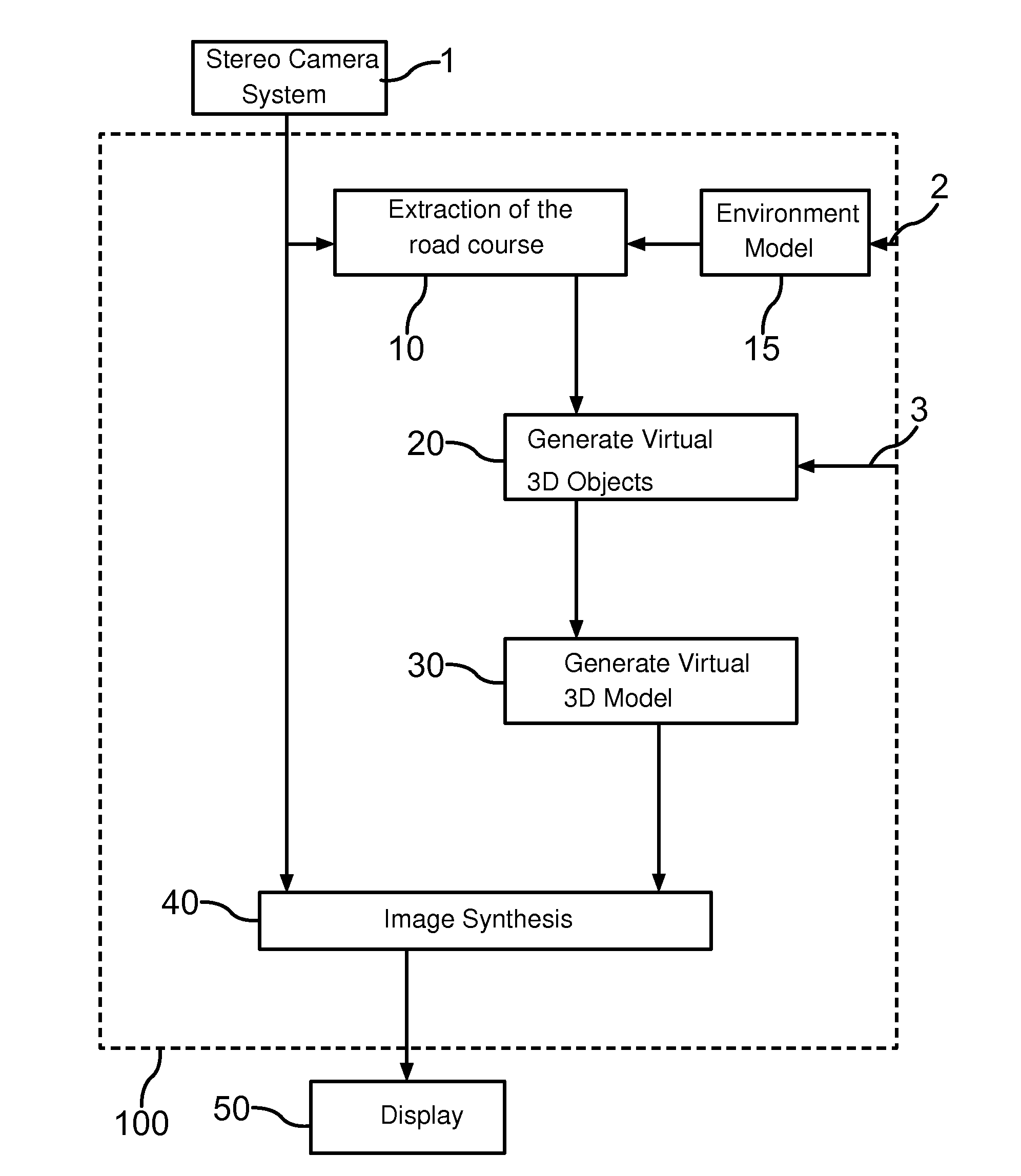
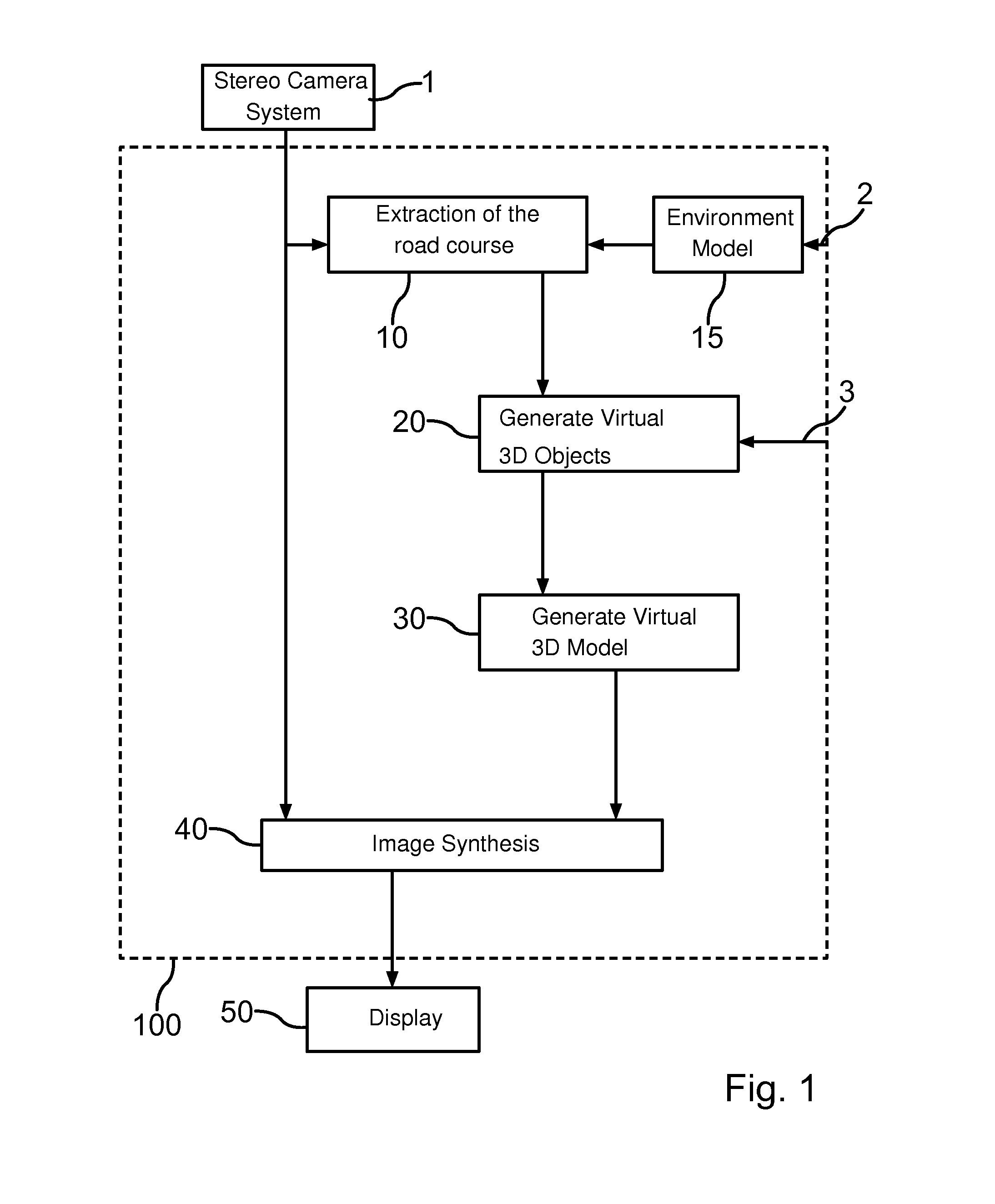
[0028]FIG. 1 depicts a flow chart according to one embodiment of the method according to the invention, as is applied, for example, on an augmented reality system 100, which runs on a device according to the invention (not shown) for displaying a digital image of a 3D object space. Such a device can, for example, be provided in a driver assistance system.

[0029]A digital image of a defined 3D object space is recorded by two vehicle-specific Cameras—a stereo camera system 1. Here, the real 3D object space corresponds to a cone of vision in the field of vision of a driver. Thus, the stereo camera system 1 provides the necessary raw data for the augmented reality system 100. The raw data comprises a digital, two-dimensional image—monocular image—of the surroundings, wherein depth information is allocated to each pixel of the image. A three-dimensional description of the recorded vehicle environment is possible by means of the depth information.

[0030]In a first step of the method, a virt...


PUM


Abstract

A method for the depiction of virtual objects in vehicle displays using one of at least one digital image of a defined real 3D object space recorded by a camera involves generating a virtual course of the road by retrieving perspective information from the digital image of the defined real 3D object space. A pre-determined virtual 3D object is then generated, which is subsequently adapted to the virtual course of the road of the defined real 3D object perspectively and with spatial accuracy. The adapted virtual 3D object is then integrated into the virtual course of the road of the defined real 3D object space.

Description

BACKGROUND AND SUMMARY OF THE INVENTION[0001]Exemplary embodiments of the invention relate to a method and a device for the perspective depiction of an artificial or virtually generated 3D object on a 2D display device.[0002]The depiction of three-dimensional geometries or of three-dimensional objects or scenes with the aid of computer systems currently plays a significant role in numerous applications. With the aid of the three-dimensional depiction, real situations can be simulated, for example in flight simulators. A further application example of three-dimensional depictions is typical in architecture, wherein here—by means of simulation of three-dimensional spaces—a representation of the sites in a virtual building is enabled.[0003]German utility model document DE 203 05 278 U1 discloses a device for the depiction of 3D objects on a 2D display device in which the 3D objects can be depicted with consideration for an observer position that can change with respect to the 2D displa...

Claims


Application Information

Patent Timeline
IPC IPC(8): B60R1/00G06T19/00
CPCG06T19/006B60R1/00B60R2300/308G01C21/3638G08G1/167B60R2300/107B60R1/31B60R1/24
Inventor GRUENLER, CHRISTIANRUH, JENS
Owner DAIMLER AG
Learn More