
Thermal Resistance Measuring Device

Inactive Publication Date: 2014-09-25
CAMBRIA
View PDF2 Cites 19 Cited by
  • Summary
  • Abstract
  • Description
  • Claims
  • Application Information

AI Technical Summary

Benefits of technology

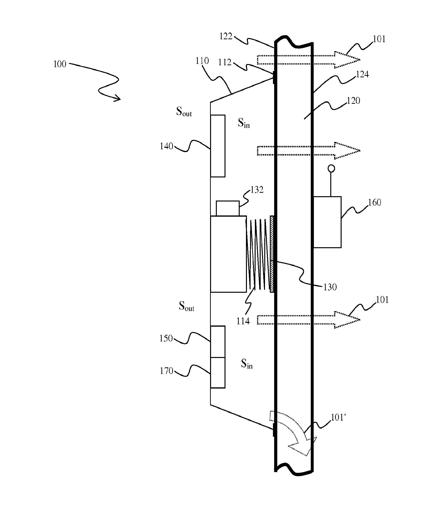
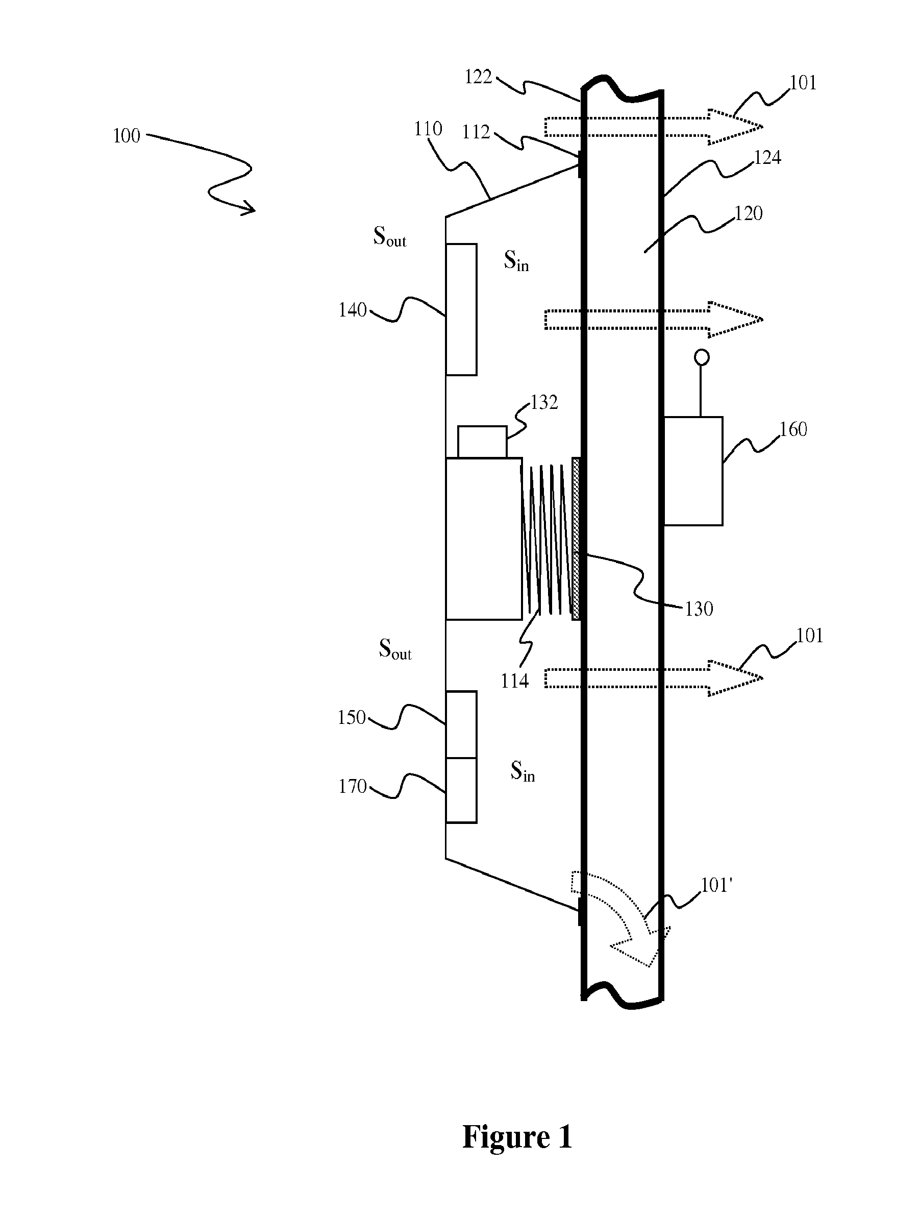
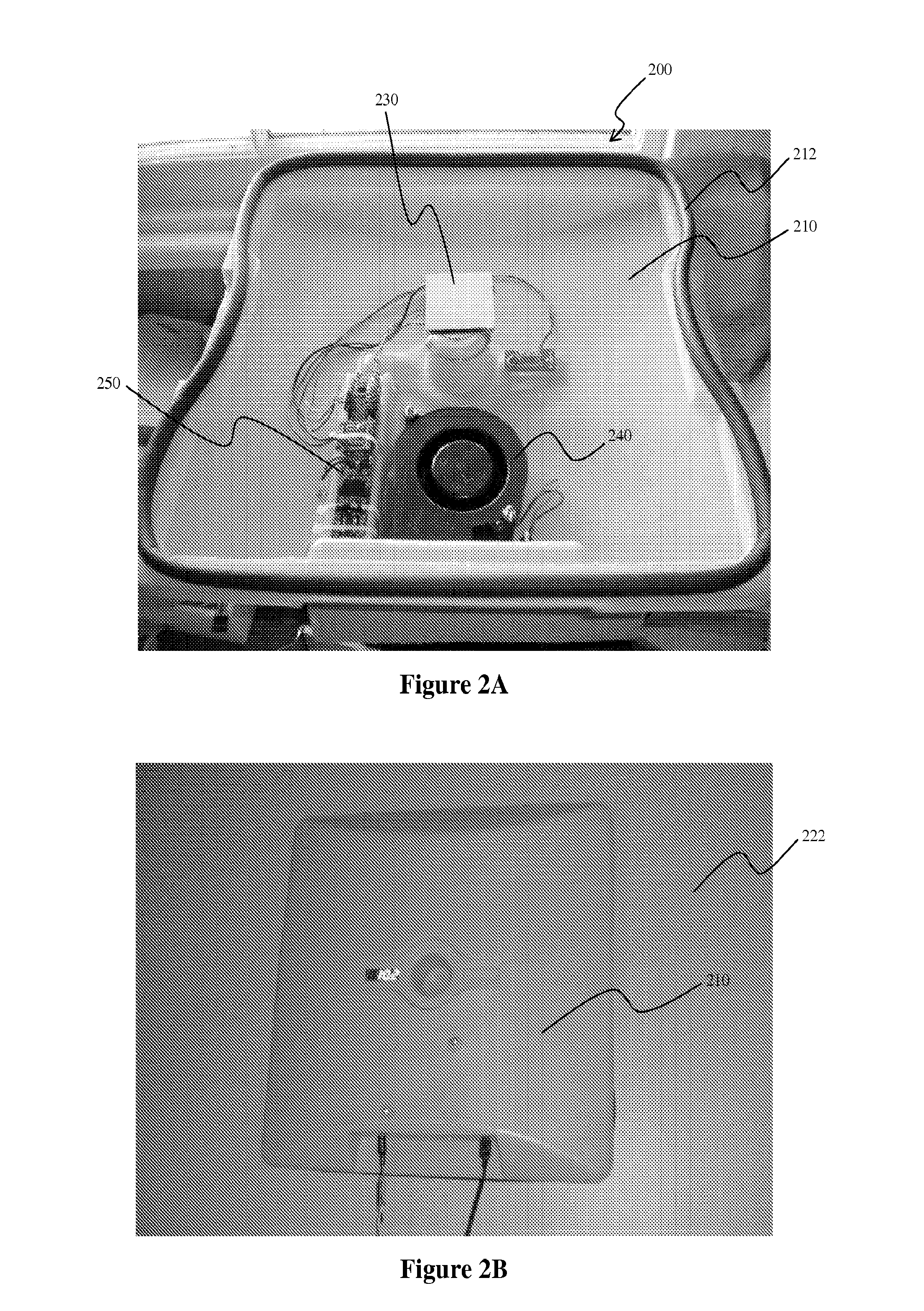
This patent is about a device and method for measuring heat transfer across a structure, usually with opposite surfaces. The device has a housing that avoids the need for a hot box and allows for accurate and easy measurement in real-time. The housing has a surface that comes into contact with the first surface and holds a heat flux transducer, which is a special sensor. The device also includes a biasing element that connects the housing and the heat flux transducer, allowing for heat transfer. A ventilation device is included to make the temperature and pressure inside the housing the same as the surrounding space, keeping the device in place on the first surface.

Problems solved by technology

Such measurements are often relatively accurate, however, demand in most cases significant space and equipment and can therefore generally not be used in situ.
Such is particularly inconvenient where heat flux measurement is performed to determine if a retrofit of a residential or industrial building in use is advisable or economically sensible.
Additional difficulties can be encountered with sizing of the hot box as heat flux from a hot box is often not perpendicular in the vicinity of the borders of the hot box.
Moreover, and depending on the type and number of thermocouples or thermopiles, sensitivity is relatively moderate and demands relatively high temperatures within the hot box.
While such devices and methods generally improve portability, various other disadvantages arise.
For example, measurement may require a significant period of time and equipment and / or calculation may be relatively complex or inaccurate.
However, the equipment is frequently very expensive and analysis may be compounded by change in environmental conditions.
Moreover, thermographic data is in most cases qualitative and unable to provide an accurate and precise quantitative assessment of thermal resistance.

Method used


Image

  • Thermal Resistance Measuring Device
  • Thermal Resistance Measuring Device
  • Thermal Resistance Measuring Device

Examples


Embodiment Construction

[0019]The inventors have discovered that heat flux across a structure can be measured in situ in a simple and accurate manner using a heat flux transducer that is placed in a housing that is configured to avoid the drawbacks normally associated with a hot box. Most advantageously, the measurement can be performed in real-time over any desired period of time at variable conditions at one side (or both sides) of the structure. Viewed from a different perspective, it should be appreciated that contemplated devices provide significant improvement over many aspects of heretofore known devices, particularly with respect to in situ use, portability, and accuracy, which is at least in part facilitated by taking advantage of the Seebeck effect of Peltier elements where such elements are used “in reverse”.

[0020]In particularly preferred methods and devices, the heat flux sensor is a thermoelectric sensor (Peltier element), which provides various advantages that are normally not achieved using...


PUM


Abstract

Contemplated devices and methods allow for simple and accurate measurement of static and dynamic heat flux and heat capacity of a structure in situ. Especially preferred devices and methods use a thermally equilibrated housing that encloses a thermoelectric sensor and an associated microprocessor and external temperature sensor.

Description

[0001]This application claims priority to our copending U.S. provisional application with the Ser. No. 61 / 627845, which was filed Oct. 20, 2011.FIELD OF THE INVENTION[0002]The field of the invention is devices and methods of in situ measurement of heat flux through a building envelope.BACKGROUND OF THE INVENTION[0003]Heat flux determination is an important tool in the construction and other industries to evaluate insulative properties and heat loss in various structures, and numerous devices and methods are known to measure heat flux. For example, ASTM C1363-11 describes a standard test method for thermal performance of building materials and envelope assemblies in which a hot box device is used to provide a heat source and a thermocouple or thermopile. The hot box is typically used in conjunction with another thermal sensor or thermocouple / thermopile that is placed opposite the structure to be measured. Such measurements are often relatively accurate, however, demand in most cases ...

Claims


Application Information

Patent Timeline
IPC IPC(8): G01K17/06
CPCG01N25/18G01K17/06G01K17/20
Inventor THRESHER, WAYNE CARLMCKINNON, CLINTON
Owner CAMBRIA
Learn More