
Multifunctional machine

a multi-functional machine and cutting tool technology, applied in the direction of manufacturing tools, grinding machine components, portable power-driven tools, etc., can solve the problems that cutting tools with openings in other shapes cannot be installed on the output shaft, cutting tools capable of being connected to the output shaft are limited in type, etc., to reduce the wear of the centering element and not increase the cost

Inactive Publication Date: 2014-10-02
POSITEC POWER TOOLS (SUZHOU) CO LTD
View PDF52 Cites 17 Cited by
  • Summary
  • Abstract
  • Description
  • Claims
  • Application Information

AI Technical Summary

Benefits of technology

This invention has the advantage of connecting different types of cutting tools to an oscillatory power tool, making it more versatile and convenient. The friction force between the two surfaces is strong enough to transmit the rotating power of the tool to the cutting tool and prevent it from slipping. The design also allows for easy assembly and disassembly of the cutting tool, and reduces wear on the parts. A centering element is provided to ensure accurate alignment, and a locating element is provided for different types of cutting tools.

Problems solved by technology

However, the above mentioned oscillatory power tool is disadvantaged in that: the premise of installing the cutting tool on the output shaft is that the star-shaped opening of the cutting tool is matched with the convex portion of the output shaft; otherwise, cutting tools with openings in other shapes cannot be installed on the output shaft.
So, the cutting tools capable of being connected to the output shaft are limited in type.

Method used


Image

  • Multifunctional machine
  • Multifunctional machine
  • Multifunctional machine

Examples


first embodiment

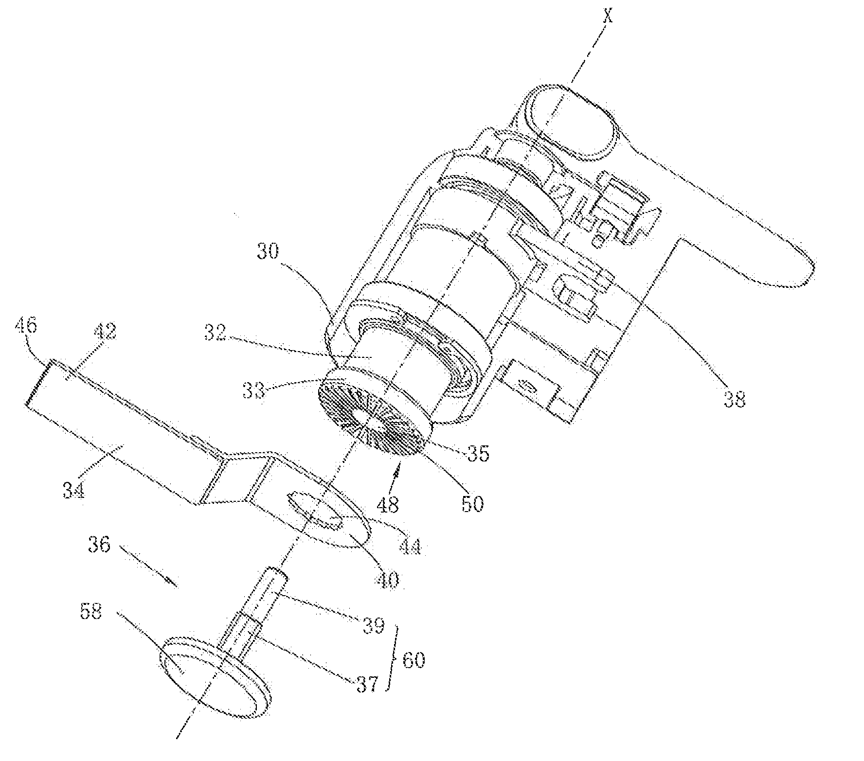
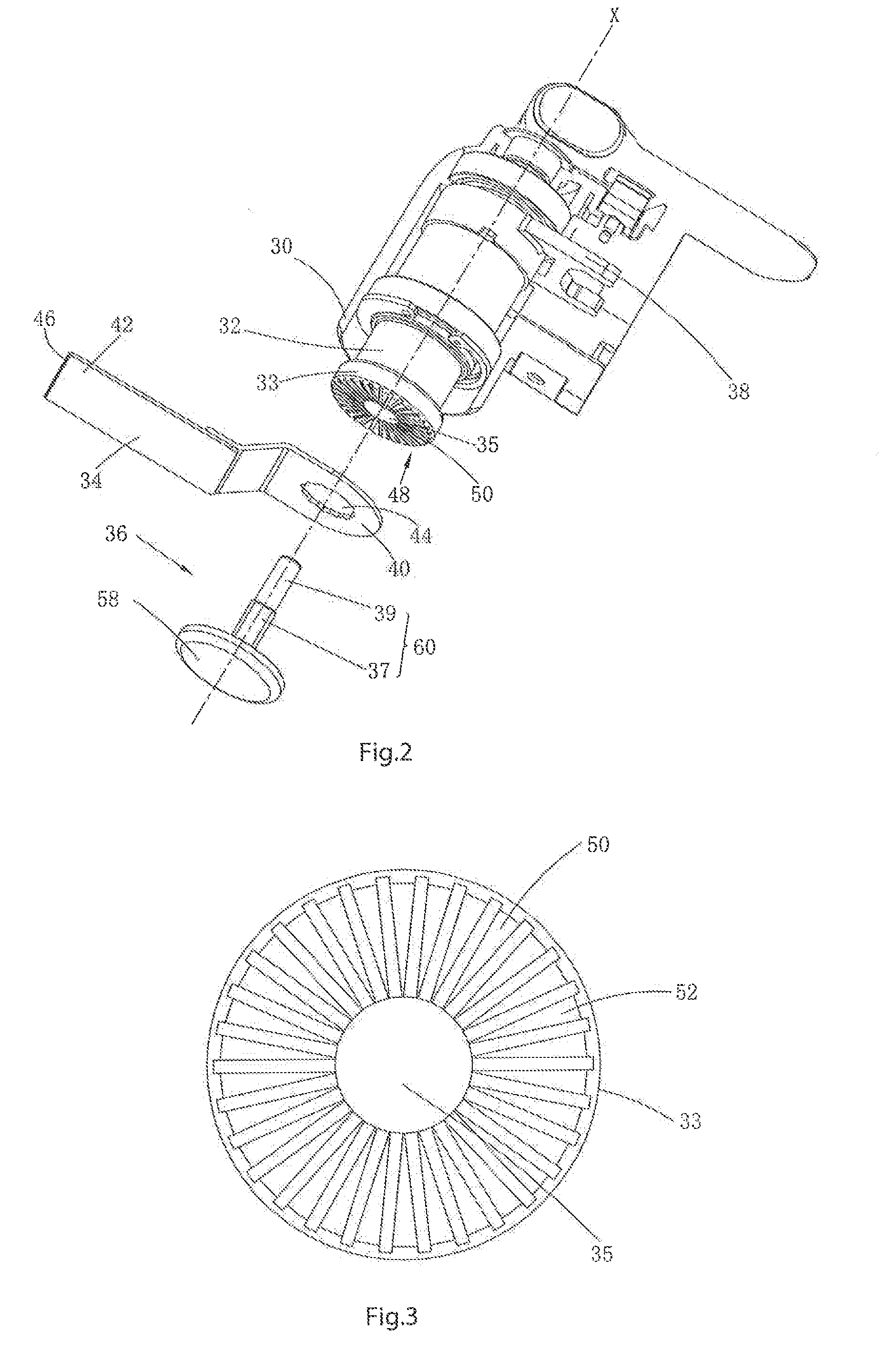
[0162]In this embodiment, the friction surface 50 is formed by several prominent ribs 52. Of course, other friction surfaces described in the first embodiment also apply.

second embodiment

[0163]The centering element of the invention is not limited to the description in the The following are specific description of centering elements in other shapes.

[0164]As shown in FIG. 18, FIG. 19, FIG. 20 and FIG. 21, in the third embodiment of the invention, the cutting tool 34b is basically structurally the same as the cutting tool 34 in the second embodiment. The cutting tool 34b also has a securing section 40b and a cutting portion 42b. The securing section 40b is provided with a connecting hole 44b. However, the shape of the connecting hole 44b is different from that of the connecting hole 44 of the cutting tool 34. The connecting hole 44b includes eight round bumps 104b extending in the radial direction. Adjacent round bumps 104b are continuously connected through curve segments 106b.

[0165]Relative to change of the connecting hole 44b, the centering element 82b is also different from the centering element 82 in the second embodiment. Wherein the first surface 86b, bumps 10...

fifth embodiment

[0190]FIGS. 27-30 illustrate several different types of cutting tools to clearly describe the invention.

[0191]Refer to FIG. 27. The first cutting tool 234a is a straight saw blade comprising a first securing section 258a and a first cutting portion 260a, wherein the first securing section 258a is connected to the output shaft 232. The first securing section 258a is provided with a first connecting hole 262a for penetration by the fastener 236. The first connecting hole 262a is the shape of regular dodecagon, and the diameter of the minimum incircle is d1. The tail end of the first cutting portion 260a is provided with a teeth 264a with cutting function.

[0192]Refer to FIG. 28. The second cutting tool 234b is a straight saw blade comprising a second securing section 258b and a second cutting portion 260b, wherein the second securing section 258b is connected to the output shaft 232. The second securing section 258b is provided with a second connecting hole 262b for penetration by the ...


PUM


Abstract

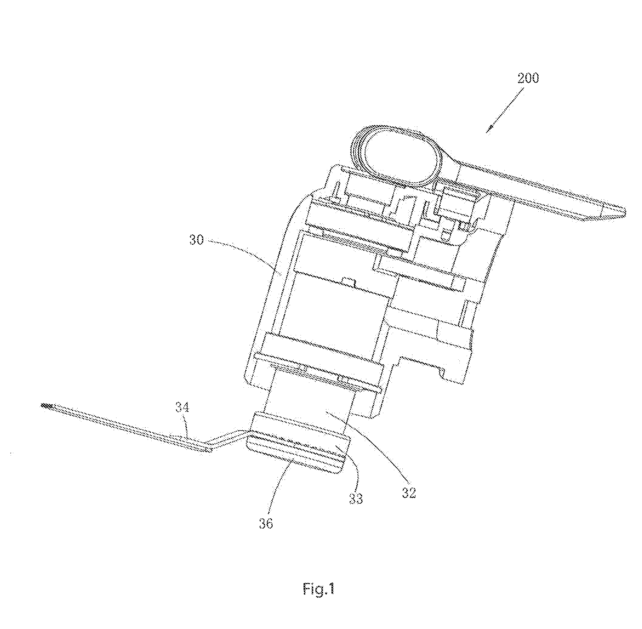
An oscillatory power tool comprising: an output shaft for mounting a cutting tool and driving the cutting tool in an oscillating rotary motion; a fastener for fastening the cutting tool to the output shaft; the cutting tool comprising a securing section being capable of connecting with the output shaft; a driving section disposed on the free end of the output shaft for engaging with the securing section of the cutting tool; the driving section having a friction surface for contacting a surface of the securing section. Through close fit between the friction surface and the upper surface of the securing section, the oscillatory power tool can be connected with different types of cutting tools, thus greatly improving the universality and convenience of the oscillatory power tool.

Description

TECHNICAL FIELD[0001]The invention relates to an oscillatory power tool, in particular to an oscillatory power tool capable of using various types of cutting tools.DESCRIPTION OF THE RELATED ART[0002]Oscillatory power tools are common handheld oscillatory power tools in the industry. The working principle is that the output shaft rotates and oscillates around its own axis to drive the cutting tool accessories installed at the tail end of the output shaft to oscillate. Common cutting tool accessories include straight saw blades, circular saw blades, triangular sanding discs, spade scrapers, etc. Therefore, different cutting tool accessories installed on the output shaft by the user can realize various operation functions, such as sawing, cutting, grinding and scrapping to be met different working demands. The traditional oscillatory power tool is provided with a form-fit mechanism for transmitting torque between the cutting tool and the output shaft. For example, a cutting tool is pr...

Claims


Application Information

Patent Timeline
Patent Type & Authority Applications(United States)
IPC IPC(8): B26D7/26B26D1/12
CPCB25F1/00B24B23/04B26D7/2614B24B45/00B26D1/12B24B27/08B25F3/00
Inventor BROWN, WARRENSZOMMER, HARRYGERHARDT, GRAHAMGU, HUAWU, HAIQUANLI, HUI
Owner POSITEC POWER TOOLS (SUZHOU) CO LTD
Learn More