Hydraulic fracture monitoring using active seismic sources with receivers in the treatment well

a technology of seismic source and hydraulic fracture, which is applied in the field of system and method for monitoring hydraulic fracture, can solve the problems of early water breakthrough, unintended fracturing, and decrease the effectiveness of water flood

Active Publication Date: 2014-10-02
SHELL USA INC
View PDF5 Cites 31 Cited by
  • Summary
  • Abstract
  • Description
  • Claims
  • Application Information

AI Technical Summary

Benefits of technology

[0006]In accordance with preferred embodiments of the invention there is provided a system and method for actively monitoring fracture growth that is not dependent on detection of microseismic signals. The invention includes the u...

Problems solved by technology

Such injection often needs to occur at high pressures, occasionally exceeding the fracture pressure and leading to unintended fracturing of the formation and fluids being injected “out of zone.” This ...

Method used


Image

  • Hydraulic fracture monitoring using active seismic sources with receivers in the treatment well
  • Hydraulic fracture monitoring using active seismic sources with receivers in the treatment well

Examples


Embodiment Construction

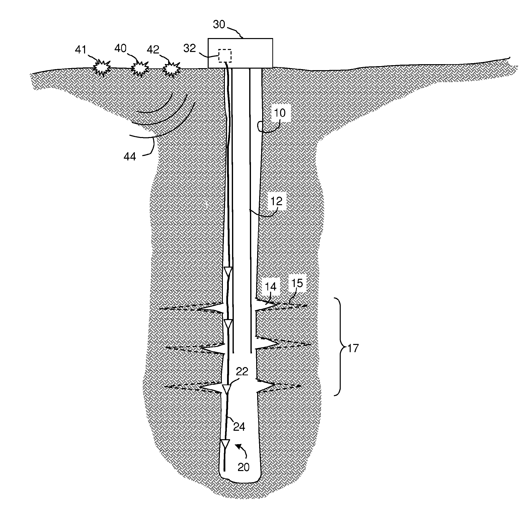
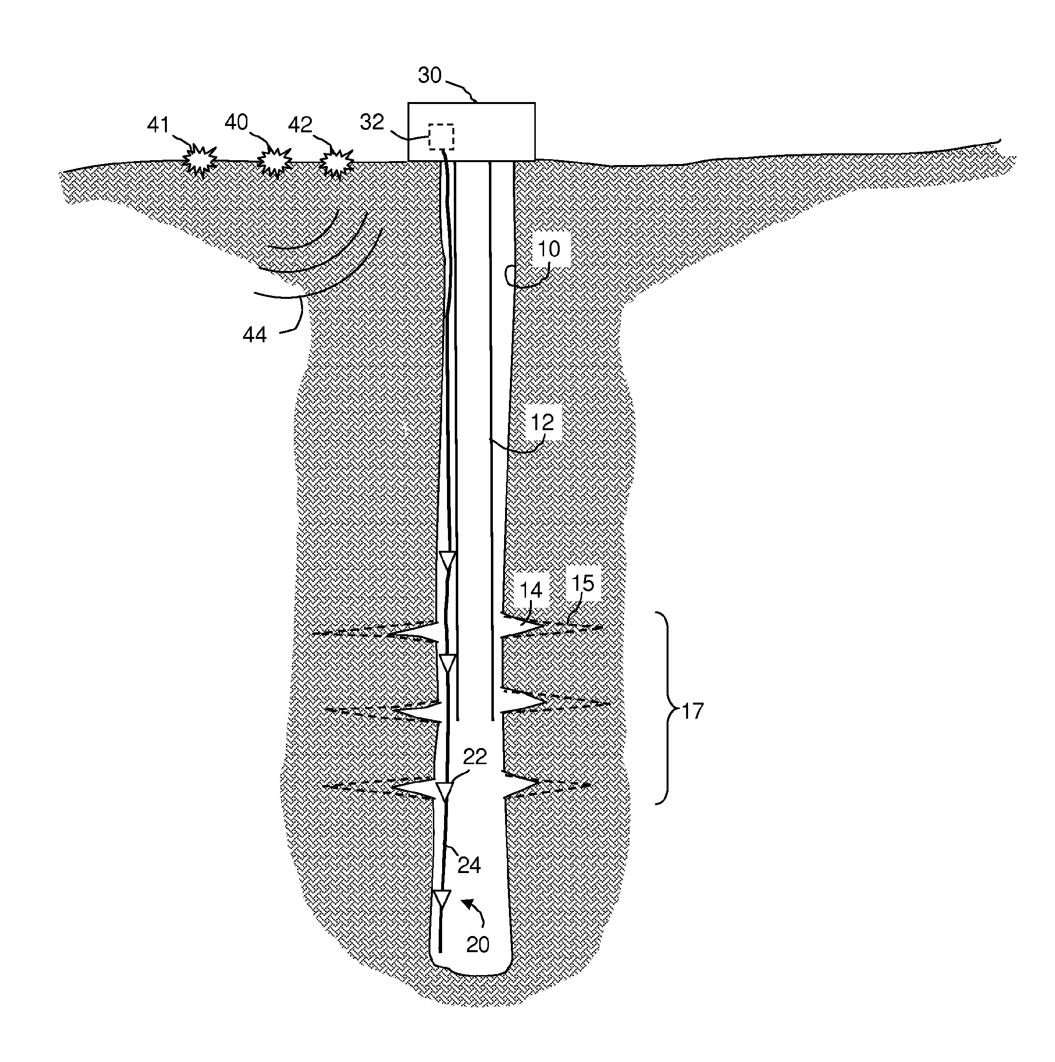
[0015]Referring to the Figure, a wellbore 10 contains a length of tubing 12 and a sensor array 20. Wellbore 10 may be cased or un-cased and there may or may not be cement in the annulus adjacent to the borehole wall. Without affecting the concepts disclosed herein, well 10 may contain one or more components such as are known in the art, including but not limited to packers, guide shoes, float shoes, float collars, stage collars, multiple tubing strings, sandscreens, perforating guns, etc (all not shown), and one or more zones in the well may be cemented or otherwise sealed or isolated. As discussed below, the well is subjected to a hydraulic fracturing force that causes fractures 14 in the formation surrounding the borehole. During fracturing, fractures 14 grow outwardly from the well, as shown in phantom by reference numeral 15. The portion of the formation in which fractures 14 are formed will be referred to as the fracture zone 17.

[0016]Sensor array 20 preferably includes a plura...


PUM


Abstract

A method for obtaining information about a hydraulic fracturing operation in a fracture zone in a well, comprises a) providing at least one acoustic sensor in the well and at least one acoustic source, b) injecting fracturing fluid into the well so as to cause fractures in a fracture zone in the surrounding formation, c) using the acoustic source to send an acoustic signal and using the acoustic receiver to receive the signal, d) repeating step c) at least once, and e) processing the received signals using a microprocessor so as to obtain information about the fractures. The source may be at the earth's surface or in a second well. Step e) may comprise measuring first-arriving acoustic waves or measuring reflected or diffracted acoustic waves. The information gained in step e) may be used to control the injection of fracturing fluid or detect out-of-zone water injection.

Description

RELATED CASES[0001]Not applicable.FIELD OF THE INVENTION[0002]The invention relates to a system and method for monitoring hydraulic fracturing using vertical seismic profiling techniques.BACKGROUND OF THE INVENTION[0003]In the production of hydrocarbons from subsurface formations, it is common to “hydraulically fracture” a formation in order to increase its permeability, which in turn enhances its productivity. Typically, a fracturing fluid is injected under pressure into the formation through an injection well. In order to determine the effectiveness of a fracturing operation, it is desirable to gain information about the rate and extent of fracturing that occurs during the injection.[0004]In water flooding operations, fluids are injected into the subsurface formation to mobilize the hydrocarbons towards producer wells. Such injection often needs to occur at high pressures, occasionally exceeding the fracture pressure and leading to unintended fracturing of the formation and fluids...

Claims


Application Information

Patent Timeline
IPC IPC(8): E21B47/14E21B43/26
CPCE21B43/26E21B47/02208E21B47/082E21B47/14G01V2210/646G01V2210/6122E21B47/101E21B47/0224E21B47/085E21B47/107
Inventor WILLS, PETER BERKELEYGRANDI KARAM, SAMAMTHAMESTAYER, JEFFERY JOSEPHUGUETO, GUSTAVO ANTONIOLOPEZ, JORGE LOUIS
Owner SHELL USA INC
Why Eureka
Try Eureka