Eureka AIR delivers breakthrough ideas for toughest innovation challenges, trusted by R&D personnel around the world.

Method for making a current-perpendicular-to-the-plane (CPP) magnetoresistive (MR) sensor with reduced-width self-aligned top electrode

Active Publication Date: 2014-10-02
WESTERN DIGITAL TECH INC
View PDF3 Cites 3 Cited by
  • Summary
  • Abstract
  • Description
  • Claims
  • Application Information

AI Technical Summary

Benefits of technology

The invention is about a method for making a CPP-MR sensor structure with a top electrode that is self-aligned and has a width less than the sensor track width. A pair of walls is fabricated above the biasing layers to act as a mask during ion milling and remove outer portions of the electrode layer. The resulting top electrode is self-aligned in the center of the sensor. Overall, this method allows for the creation of a precise and aligned top electrode, improving the performance and accuracy of the CPP-MR sensor.

Problems solved by technology

A reduction in the sensor physical TW is difficult because of the small dimensions required.

Method used


Image

  • Method for making a current-perpendicular-to-the-plane (CPP) magnetoresistive (MR) sensor with reduced-width self-aligned top electrode
  • Method for making a current-perpendicular-to-the-plane (CPP) magnetoresistive (MR) sensor with reduced-width self-aligned top electrode
  • Method for making a current-perpendicular-to-the-plane (CPP) magnetoresistive (MR) sensor with reduced-width self-aligned top electrode

Examples


Embodiment Construction

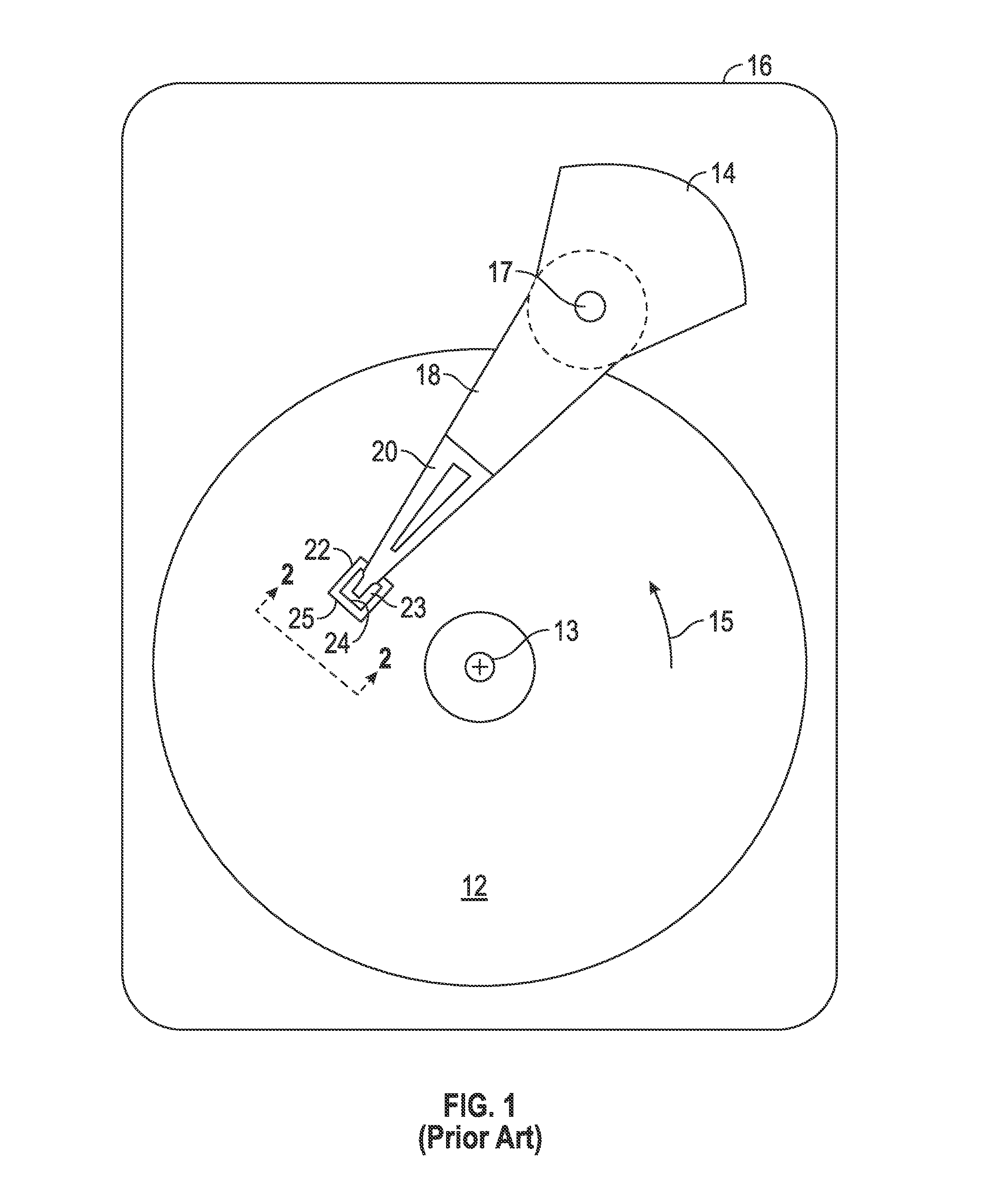
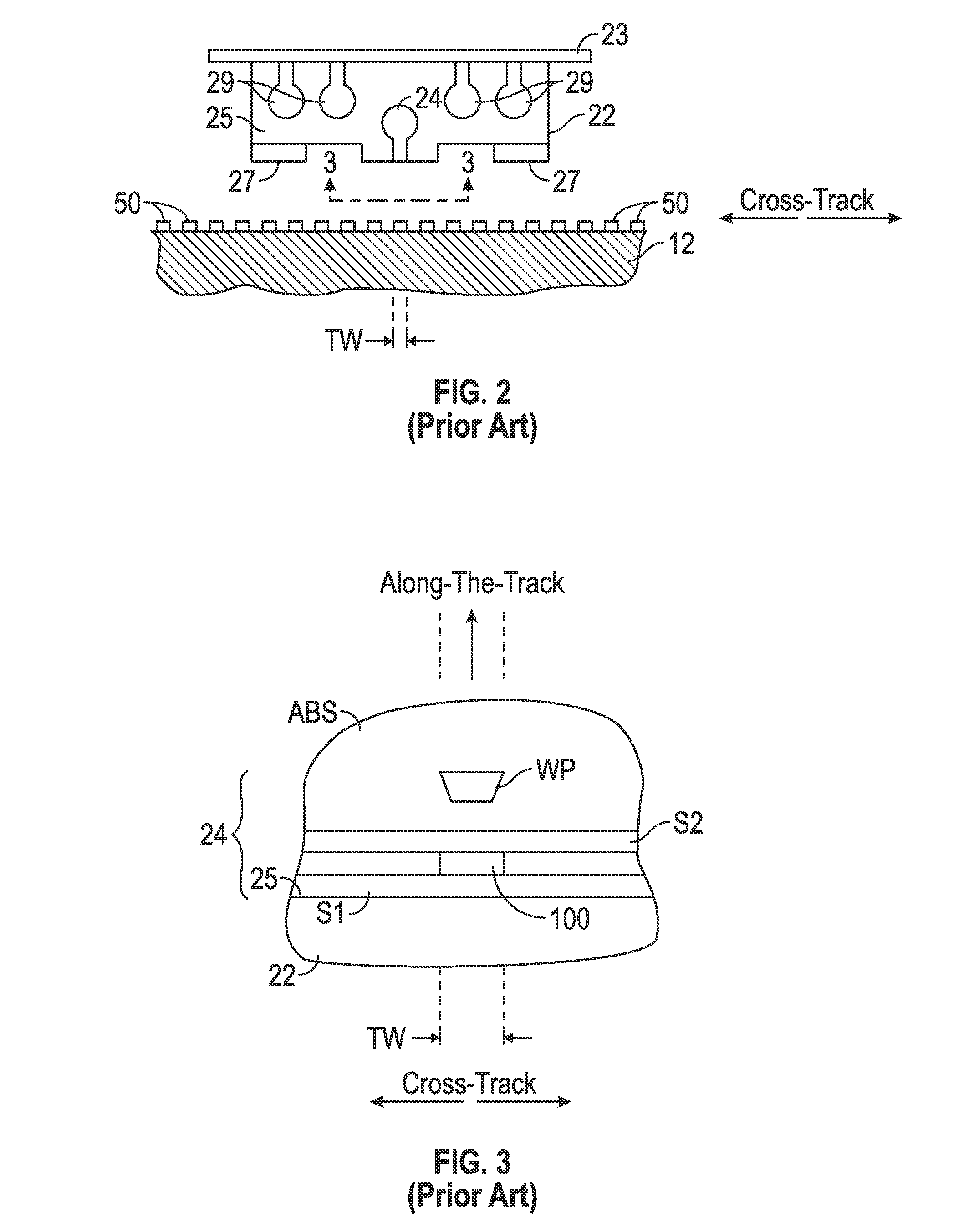
[0016]The CPP magnetoresistive (MR) sensor made by the method of this invention has application for use in a magnetic recording disk drive, the operation of which will be briefly described with reference to FIGS. 1-3. FIG. 1 is a block diagram of a conventional magnetic recording hard disk drive. The disk drive includes a magnetic recording disk 12 and a rotary voice coil motor (VCM) actuator 14 supported on a disk drive housing or base 16. The disk 12 has a center of rotation 13 and is rotated in direction 15 by a spindle motor (not shown) mounted to base 16. The actuator 14 pivots about axis 17 and includes a rigid actuator arm 18. A generally flexible suspension 20 includes a flexure element 23 and is attached to the end of arm 18. A head carrier or air-bearing slider 22 is attached to the flexure 23. A magnetic recording read / write head 24 is formed on the trailing surface 25 of slider 22. The flexure 23 and suspension 20 enable the slider to “pitch” and “roll” on an air-bearing...


PUM

PropertyMeasurementUnit
Angleaaaaaaaaaa
Electrical resistanceaaaaaaaaaa

Abstract

A method for making a current-perpendicular-to-the-plane magnetoresistive sensor structure produces a top electrode that is “self-aligned” on the top of the sensor and with a width less than the sensor trackwidth. A pair of walls of ion-milling resistant material are fabricated to a predetermined height above the biasing layers at the sensor side edges. A layer of electrode material is then deposited onto the top of the sensor between the two walls. The walls serve as a mask during angled ion milling to remove outer portions of the electrode layer. The height of the walls and the angle of ion milling determines the width of the resulting top electrode. This leaves the reduced-width top electrode located on the sensor. Because of the directional ion milling using walls that are aligned with the sensor side edges, the reduced-width top electrode is self-aligned in the center of the sensor.

Description

BACKGROUND OF THE INVENTION[0001]1. Field of the Invention[0002]The invention relates generally to a current-perpendicular-to-the-plane (CPP) magnetoresistive (MR) sensor that operates with the sense current directed perpendicularly to the planes of the layers making up the sensor stack, and more particularly to a method for making a CPP-MR sensor having a top electrode with a width less than the sensor trackwidth (TW).[0003]2. Background of the Invention[0004]One type of conventional CPP-MR sensor used as the read head in magnetic recording disk drives is based on the giant magnetoresistance (GMR) effect. A GMR spin-valve sensor has a stack of layers that includes two ferromagnetic layers separated by a nonmagnetic electrically conductive spacer layer, which is typically copper (Cu). One ferromagnetic layer adjacent the spacer layer has its magnetization direction fixed, such as by being pinned by exchange coupling with an adjacent antiferromagnetic layer, and is referred to as the...

Claims


Application Information

Patent Timeline
IPC IPC(8): G11B5/39
CPCG11B5/398G11B5/3163Y10T29/49032
Inventor BRAGANCA, PATRICK MESQUITACHILDRESS, JEFFREY R.KATINE, JORDAN ASHERLI, YANGROBERTSON, NEIL LESLIESMITH, NEILVANDERHEIJDEN, PETRUS ANTONIUSWERNER, DOUGLAS JOHNSON
Owner WESTERN DIGITAL TECH INC
Why Eureka
Eureka Blog
Learn More