Hinge antenna and foldable electronic device using the same

a technology of folding electronic devices and antennas, applied in the direction of antenna details, antenna details, details of portable computers, etc., can solve the problems of affecting the reception of antenna signals, reducing the reducing the effect of effective transmission distance and signal quality, so as to achieve effective shortening of the manufacturing process and improving yield

Inactive Publication Date: 2014-10-02
ADVANCED CONNECTEK INC
View PDF8 Cites 19 Cited by
  • Summary
  • Abstract
  • Description
  • Claims
  • Application Information

AI Technical Summary

Benefits of technology

[0015]With the hinge antenna and the foldable electronic device with the hinge antenna provided by the present invention, the effects of structure stabilization, assembly simplification and appearance unification can be achieved. Furthermore, the manufacturing process can be effectively shortened and the yield can be improved as a result.

Problems solved by technology

Since signal degradation, such as insertion loss, occurs when signals are transmitted by using coaxial cables, the effective transmission distance and signal quality are reduced.
In addition, such signal degradation is more severe in the coaxial cable during wireless transmission in higher frequency.
Moreover, the shell of the laptops is commonly made of metal which creates shielding effect and as results the signal reception of the antenna is affected.

Method used


Image

  • Hinge antenna and foldable electronic device using the same
  • Hinge antenna and foldable electronic device using the same
  • Hinge antenna and foldable electronic device using the same

Examples


first embodiment

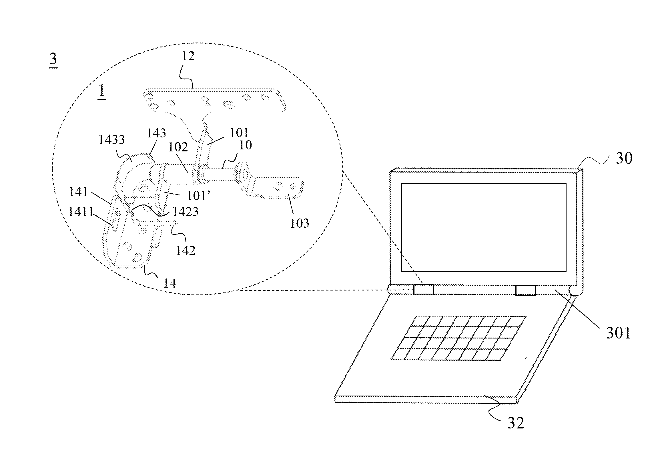
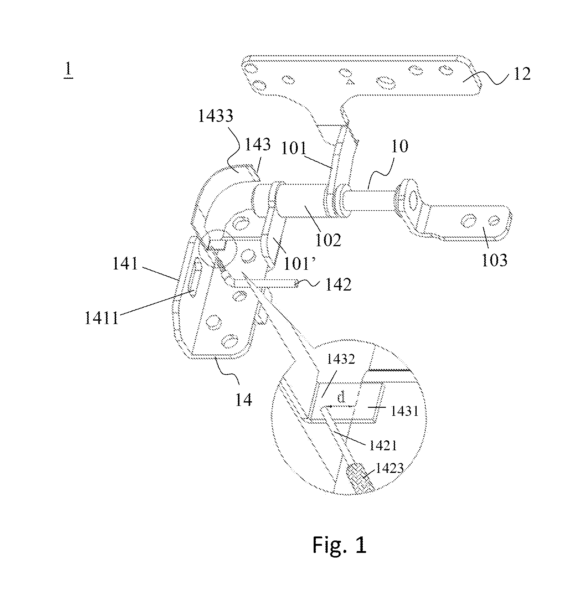
[0025]First, please refer to FIG. 1. FIG. 1 is a schematic view of a hinge antenna according to the present invention. As shown in FIG. 1, the hinge antenna 1 includes a metal hinge 10, a first metal connecting plate 12 and a second metal connecting plate 14. One end of the first metal connecting plate 12 and one end of the second metal connecting plate 14 is connected to a metal joint plate 101 and a metal joint plate 101′ respectively. The metal hinge 10 is jointed the first metal connecting plate 12 through the metal joint plate 101 and metal hinge 10 is also jointed the second metal connecting plate 14 through the metal joint plate 101′. The metal hinge 10 further includes a metal shaft 102 which is arranged and penetrated within the metal joint plate 101 and the metal joint plate 101′, such that the first metal connecting plate 12 and the second metal connecting plate are rotated by the metal shaft 103 with respect to the metal hinge 10. The metal shaft 10, the metal joint plat...

second embodiment

[0031]Next, please refer to FIG. 3. FIG. 3 is a schematic view of a hinge antenna according to the present invention. As shown in FIG. 3, a hinge antenna 2 includes a metal hinge 20, a first metal connecting plate 22 and a second metal connecting plate 24. One end of the first metal connecting plate 22 and one end of the second metal connecting plate 24 is connected to a metal joint plate 201 and a metal joint plate 201′ respectively. The metal hinge 20 is jointed the first metal connecting plate 22 through the metal joint plate 201 and the metal hinge 20 is jointed the second metal connecting plate through the metal joint plate 201′. The metal hinge 201′ further includes a metal shaft 202 and the metal shaft 202 is penetrated through the metal joint plate 201 and the metal joint plate 201′ such that the first metal connecting plate 22 and the second metal connecting plate 24 are rotated by the metal shaft 202 with respect to the metal hinge 20. Above metal hinge 20, the first metal...


PUM


Abstract

A hinge antenna comprises a metal hinge, a first metal connecting plate and a second metal connecting plate. The hinge antenna further comprises a microwave substrate, a signal feeding line, and a conductor, wherein the conductor is electrically connected to the microwave substrate and extended from the microwave substrate. Furthermore, the feed line of the signal feeding line is electrically connected to the microwave substrate and the ground line of the signal feeding line is electrically connected to the metal hinge, the first metal connecting plate, the second metal connecting plate, and an outside metal shield so that the metal hinge, the first metal connecting plate, the second metal connecting plate, and the outside metal shield can serve as a ground. The aforementioned configuration is utilized to form an antenna loop. In addition, the configuration of this antenna can be built in the interior space of the foldable electronic device.

Description

BACKGROUND OF THE INVENTION[0001]1. Technical Field[0002]The present invention relates to a hinge antenna, and in particular to a hinge antenna can be used in a foldable electronic device. The antenna element is integrated with a hinge within the foldable electronic device, such that the hinge antenna can be accommodated within the interior space in the foldable electronic device. With such antenna structure, the effects of stabilization in structure, simplification in assembly and unification in appearance can be achieved.[0003]2. Description of the Prior Art[0004]With the rapid development of technologies, varieties of portable 3C electronic devices provide convenience for human life, and thus become indispensable. In recent years, due to the rapid growth of wireless communication, a large amount of data is transmitted to portable 3C electronic devices via wireless networks. As been an integrated configuration of portable 3C electronic device, it is necessary for antennas to be bu...

Claims


Application Information

Patent Timeline
Patent Type & Authority Applications(United States)
IPC IPC(8): H01Q1/22
CPCH01Q1/2266H01Q1/243G06F1/1616G06F1/1698G06F1/1681
Inventor HSIAO, FU-RENCHEN, CHIH-FAN
Owner ADVANCED CONNECTEK INC
Why Eureka
Try Eureka