Lens mount with conductive glue pocket for grounding to a circuit board

a technology of circuit board and lens body, applied in the direction of cross-talk/noise/interference reduction, electrical apparatus contruction details, printed circuit non-printed electric components association, etc., can solve the problems of improper grounding, damage such components, and difficulty in attaching the lens body to the circuit board, so as to prevent electrical damage to electrical components and prevent electrical damage to camera modules

Active Publication Date: 2014-10-02
STMICROELECTRONICS INT NV
View PDF7 Cites 7 Cited by
  • Summary
  • Abstract
  • Description
  • Claims
  • Application Information

AI Technical Summary

Benefits of technology

[0006]According to one aspect of the present disclosure, a cover or lens mount is grounded to a circuit board by conductive glue positioned in at least one aperture of the cover. The conductive glue is configured to electrically ground the cover to the circuit board to prevent ele

Problems solved by technology

Proper grounding poses difficulties when working with very small components of camera modules.
The conductive glue can leak or seep onto the electrical components of the circuit board, which damages such components.
Moreover, because of the relatively high viscosity of conductive glues and the very small compo

Method used


Image

  • Lens mount with conductive glue pocket for grounding to a circuit board
  • Lens mount with conductive glue pocket for grounding to a circuit board
  • Lens mount with conductive glue pocket for grounding to a circuit board

Examples


Embodiment Construction

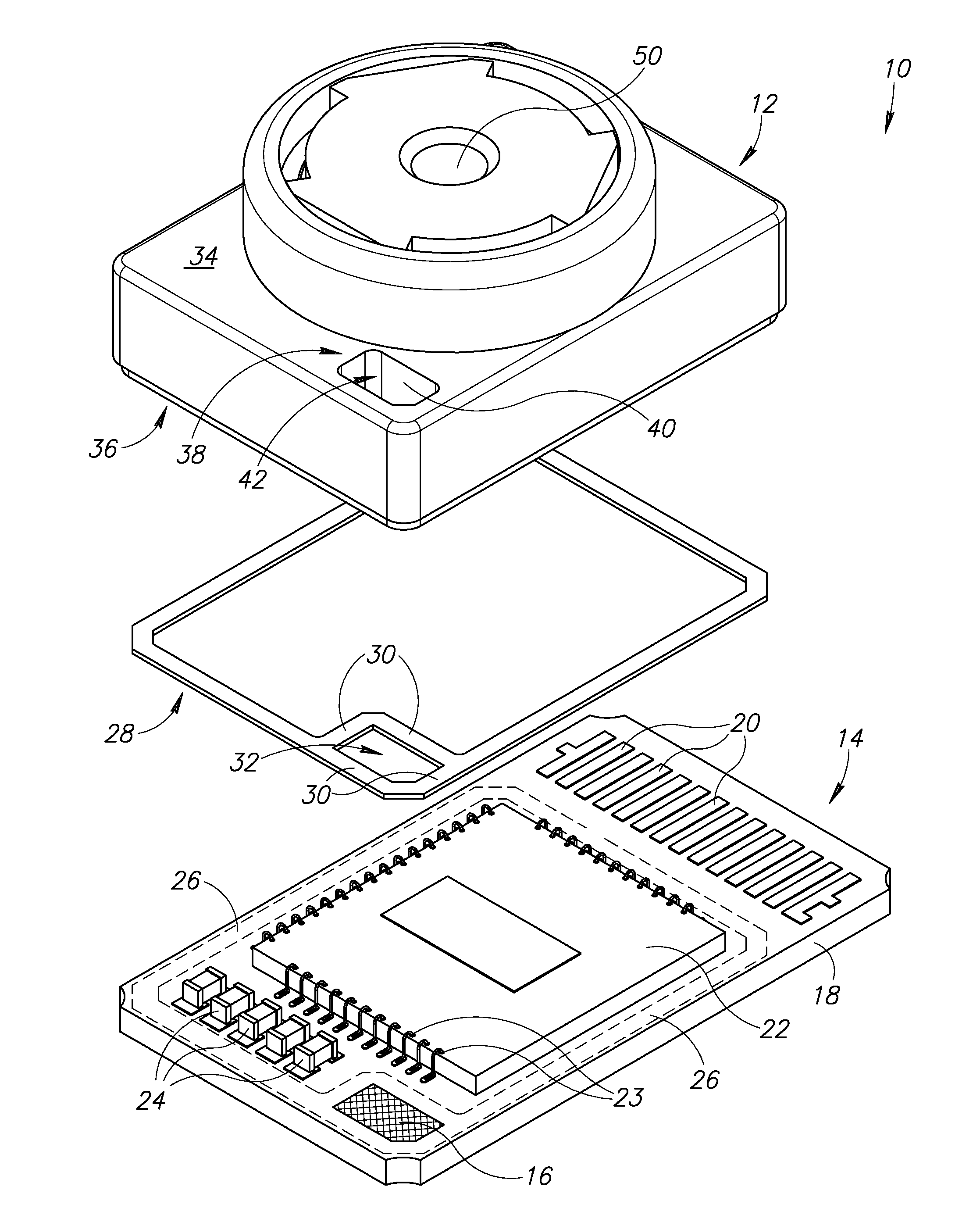
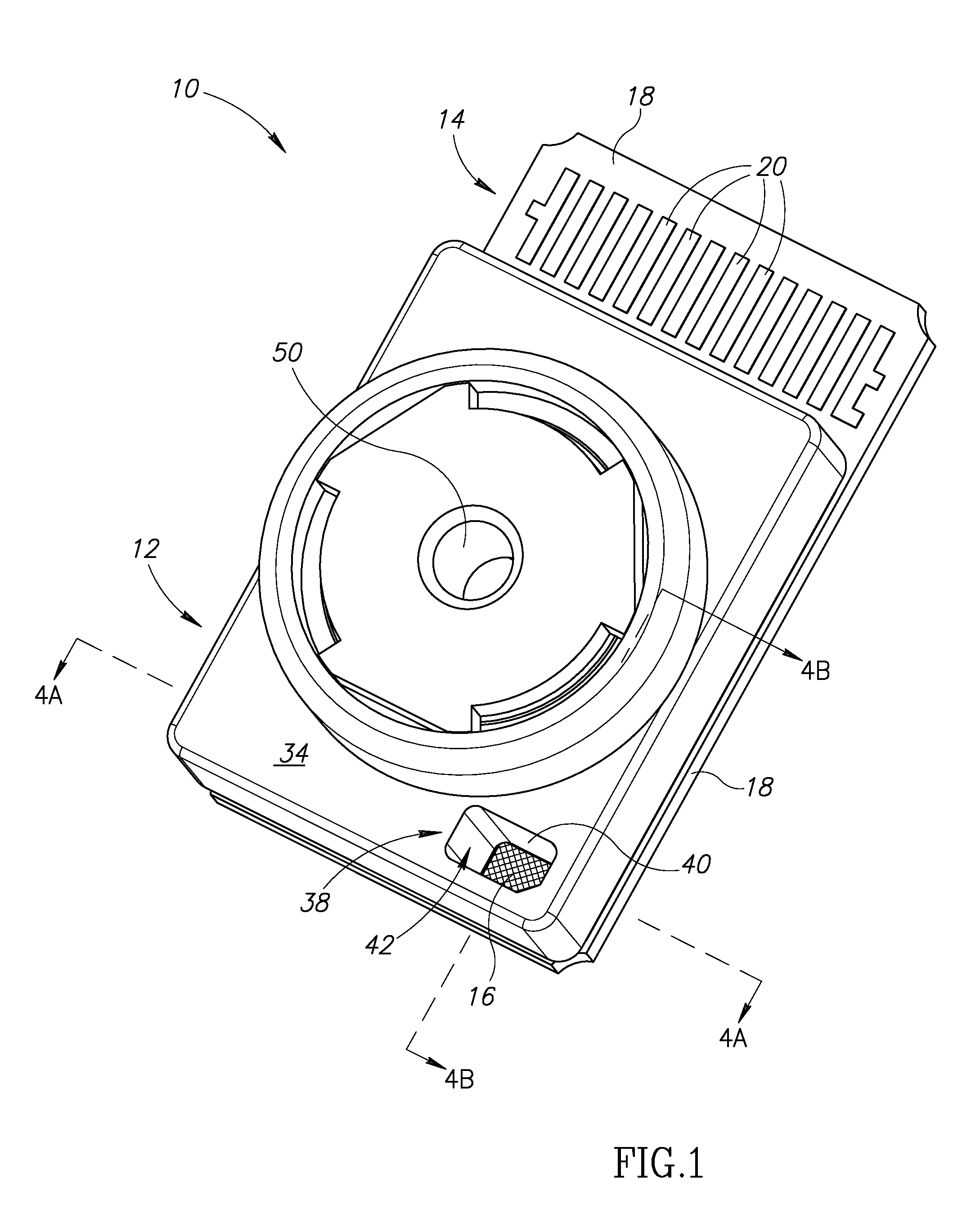
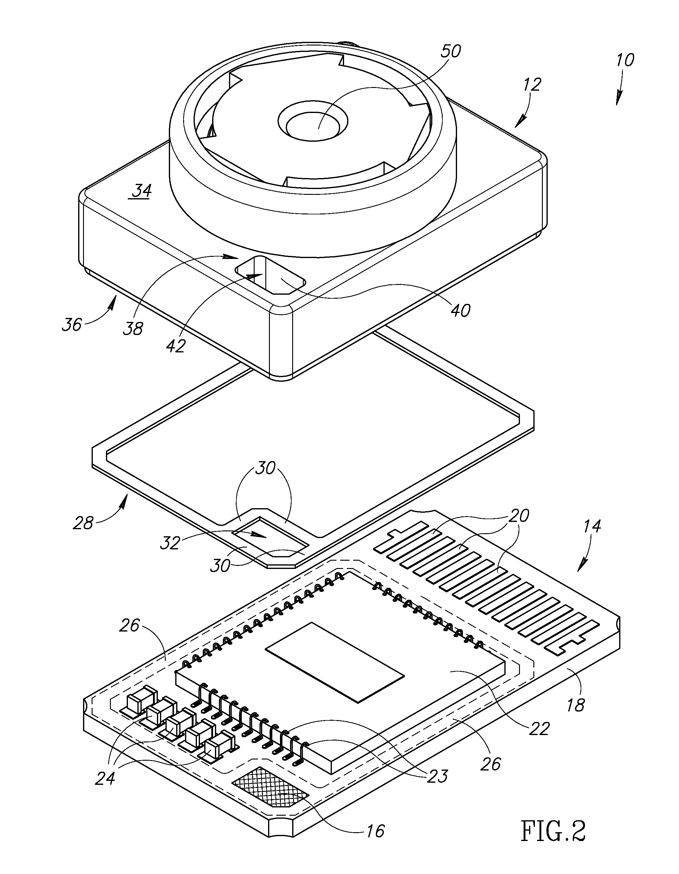
[0016]FIGS. 1 and 2 show an electronic device 10 according to one aspect of the present disclosure. The electronic device 10 includes a cover 12 and a circuit board 14. The cover 12 may be a lens mount 12. The circuit board 14 includes a grounding pad 16, a substrate 18, electrical leads 20, a sensor 22, and other electronic components 24, either passive or active, such as transistors, resistors, or capacitors. The sensor 22 may be a charge coupled device, an acoustic sensor, a light-sensitive device, or other suitable sensing device. The sensor 22 is a die or chip, which may or may not be in a separate package. For example, the die of the sensor 22 may be packaged separately and then attached to the substrate 18 or the die may be directly coupled to the substrate.

[0017]The electrical leads 20 are coupled to electrical traces in the substrate 18, which traces also couple the sensor 22 and the electronic components 24 to each other. The leads 20 can couple the device 10 to a computer...


PUM

PropertyMeasurementUnit
Thicknessaaaaaaaaaa
Diameteraaaaaaaaaa
Distanceaaaaaaaaaa

Abstract

A lens mount is attached to a circuit board and covers electrical components on the circuit board. An electrically insulating device is positioned between the lens mount and the circuit board. The circuit board includes a grounding pad adjacent the electrically insulating device. The lens mount includes an aperture aligned with the grounding pad and the electrically insulating device. A conductive glue is dispensed into the aperture to electrically ground the lens mount to the grounding pad. The electrically insulating device seals the conductive glue from the electrical components. A method of grounding a lens mount to a circuit board is provided.

Description

BACKGROUND[0001]1. Technical Field[0002]The present disclosure relates generally to electrical devices, and more particularly, to an aperture in a lens mount to electrically ground and physically attach the lens mount to a circuit board.[0003]2. Description of the Related Art[0004]Camera modules are important devices for the inputting and outputting of digital information via electronic devices. The digital camera module is becoming more and more useful in electronic devices, such as mobile phones, computers, and webcams. Due to the increasingly thinner and smaller size of electronic devices, the digital camera modules are being adapted to fit into such devices while still operating effectively. Existing lens bodies of camera modules are not directly attached to a circuit board; instead, there is typically an intervening holder / body between the lens mount and the circuit board, thereby requiring additional manufacturing steps to attach the mount to the circuit board.[0005]Moreover, ...

Claims


Application Information

Patent Timeline
IPC IPC(8): H05K1/18H05K3/22
CPCH05K1/0215H05K9/0024Y10T29/49124H05K2201/2018H05K9/0039H04N23/57H04N23/52
Inventor LIM, WEE CHIN JUDY
Owner STMICROELECTRONICS INT NV
Why Eureka
Try Eureka