Systems and methods for multi-view imaging and tomography

a multi-view imaging and tomography technology, applied in the direction of material analysis, material analysis using wave/particle radiation, instruments, etc., can solve the problems of reducing the signature of a heavy metal, and reducing the accuracy of the imag

Active Publication Date: 2014-10-02
VAREX IMAGING CORP
View PDF97 Cites 39 Cited by
  • Summary
  • Abstract
  • Description
  • Claims
  • Application Information

AI Technical Summary

Benefits of technology

[0012]Known fourth generation systems (dual-energy source with stacked detectors and algorithm) only provide projection images. Objects extending through an X-ray beam path are “squeezed” into a planar view. Except in a few simple cases, the 2-D image (with material information) may not contain sufficient information...

Problems solved by technology

Except in a few simple cases, the 2-D image (with material information) may not contain sufficient information to resolve objects that overlap in a beam path direction.
This dilutes the material signature.
However, this typically requires rotating the whole X-ray source and detector assembly as one integrated pi...

Method used


Image

  • Systems and methods for multi-view imaging and tomography
  • Systems and methods for multi-view imaging and tomography
  • Systems and methods for multi-view imaging and tomography

Examples


Embodiment Construction

Multiple X-Ray Sources by Skewed Electron Transport

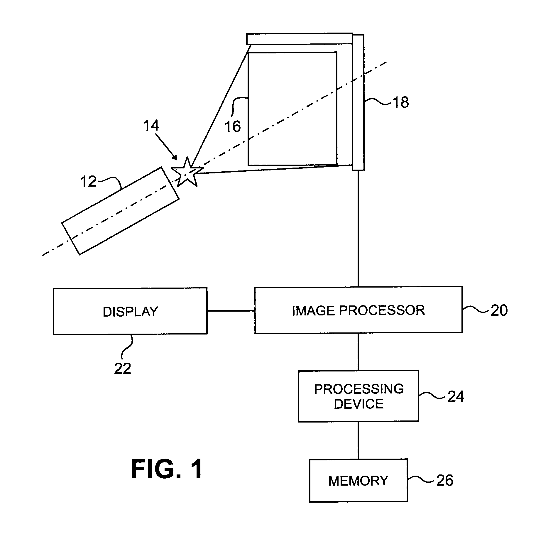
[0038]FIG. 3 is a schematic representation of a radiation scanning system 100 in accordance with an embodiment of the invention. In this example, the radiation scanning system 100 comprises a single charged particle accelerator 110, such as an electron linear accelerator, and multiple X-ray target stations 120e-120g defining respective multiple viewing locations with respect to an object 130 to be examined. The object 130 may be a cargo container, cargo conveyance, or other object, for example. The electron linear accelerator may be a Linac, available from Varian Medical Systems, Inc., Palo Alto, Calif., for example. An accelerated electron beam, which is typically generated in short pulses, for example, is transported through beam pipes 142, 144, 146 and directed by magnetic fields to impact one of the multiple targets 120a-120g to produce X-rays to scan the object 130 at different angles. An image processor 20, a display 22, a pro...


PUM


Abstract

Radiation scanning systems providing multiple views of an object in different planes and a reconstruction algorithm for reconstructing quasi-three-dimensional images from a limited number of views. A system may include bend magnets to direct accelerated charged particles to multiple targets in different viewing locations. Another system collimates radiation generated by a plurality of radiation sources into multiple beams for scanning an object at multiple angles. The object may be a cargo container, for example. The reconstruction algorithm uses an optimization algorithm and imaging and feasibility models to reconstruct quasi-three-dimensional images from the limited number of views.

Description

RELATED APPLICATION[0001]The present application claims the benefit of U.S. Provisional Application No. 61 / 798,372, which was filed on Mar. 15, 2013, is assigned to the assignee of the present invention and is incorporated by reference herein.[0002]The present application is related to U.S. patent application Ser. No. 13 / 277,833, which was filed on Oct. 20, 2011 and was published on Apr. 25, 2013 bearing U.S. Patent Publication No. 2013 / 0101156, is assigned to the assignee of the present application is incorporated by reference herein.FIELD OF THE INVENTION[0003]Radiation scanning of objects and, more particularly, radiation scanning of objects, such as cargo containers, by multiple sources, to reconstruct three-dimensional images.BACKGROUND OF THE INVENTION[0004]Radiation scanning systems used in cargo imaging technology, including land, sea, or air cargo, have advanced through multiple generations. First generation radiation scanning systems include gamma-ray sources, which are us...

Claims


Application Information

Patent Timeline
IPC IPC(8): G01V5/00
CPCG01V5/0016G01N23/046G01V5/0008G01V5/0025G01V5/0041G01V5/005G01V5/0066H05H7/22H05H9/00
Inventor CHEN, GONGYINHOLT, KEVINDRUBKA, ROBERT E.STAMMETTI, JOHNDUNCAN, MICHAEL Z.FOX, TIMOTHY R.NISIUS, DAVIDHU, MARTIN
Owner VAREX IMAGING CORP
Why Eureka
Try Eureka