Press-formed product, hot press-forming method and hot press-forming apparatus

a technology of press-forming apparatus and press-forming method, which is applied in the direction of heat treatment apparatus, manufacturing tools, shaping tools, etc., can solve problems such as deteriorating formability, and achieve the effects of suppressing heat removal, increasing forming speed, and suppressing temperature drop at the flange region

Inactive Publication Date: 2014-10-02
TOYOTA CENT RES & DEV LAB INC
View PDF2 Cites 26 Cited by
  • Summary
  • Abstract
  • Description
  • Claims
  • Application Information

AI Technical Summary

Benefits of technology

[0065]Various types of methods may be possible to suppress heat removal from the flange region of the heated steel sheet to the metal die (die and blank holder) for the purpose of suppressing the temperature fall at the flange region. For example, a heater or the like may be embedded in a metal die region that can be in contact with the flange region thereby to heat or keep the temperature of the flange region of the steel sheet. In an alternative embodiment, the forming speed may be increased to substantially reduce the time for contact between the flange region of the steel sheet and the metal die (and therefore the time for heat removal) thereby to achieve the suppression of temperature fall at the flange region. In this case, the number of shots (the number of forming operations) per one minute may be 10 spm (shot per minute) or more, preferably 15 spm or more, and more preferably 20 spm or more.
[0066]In a further embodiment, during at least a part of the time period for the forming, the metal die and the flange region of the steel sheet may be in a non-contact state or in a non-close-contact state. This allows the suppression of temperature fall to be performed simply and efficiently. Therefore, the heat removal suppressing forming step according to the present invention may preferably be a non-clamping/pressing forming step that performs the press-forming without clamping/pressing the flange region of the steel sheet by the die and the blank holder.
[0067]Such a non-clamping/pressing forming step may be performed by various methods. For example, the die and the blank holder may be controlled and driven using a servo mechanism so that the steel sheet and the metal die do not contact with each other at the flange region. In an alternative embodiment, one or more distance blocks may be disposed between the die and the blank holder. In this case, the clearance between the die and the blank holder can easily be controlled at the flange region of the street sheet by adjusting the thickness of the distance blocks. Moreover, this configuration is simple and can contribute to the high speed forming because the distance blocks are merely disp

Problems solved by technology

However, when hot-press forming is employed to produce a certain product such as deep-drawn product in which the amount of plastic deformation of

Method used


Image

  • Press-formed product, hot press-forming method and hot press-forming apparatus
  • Press-formed product, hot press-forming method and hot press-forming apparatus
  • Press-formed product, hot press-forming method and hot press-forming apparatus

Examples


example 1

(1) Hot Press-Forming Apparatus

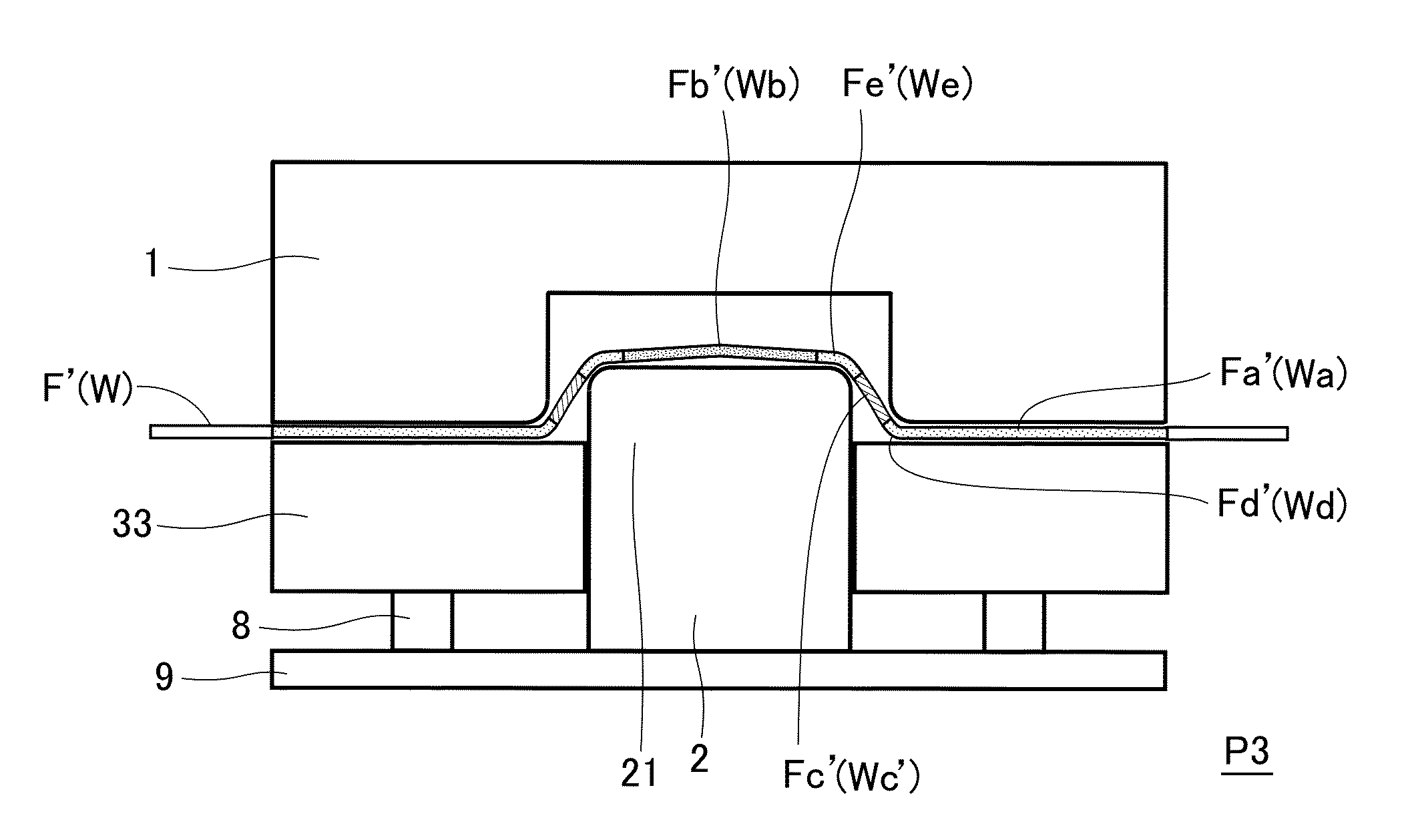
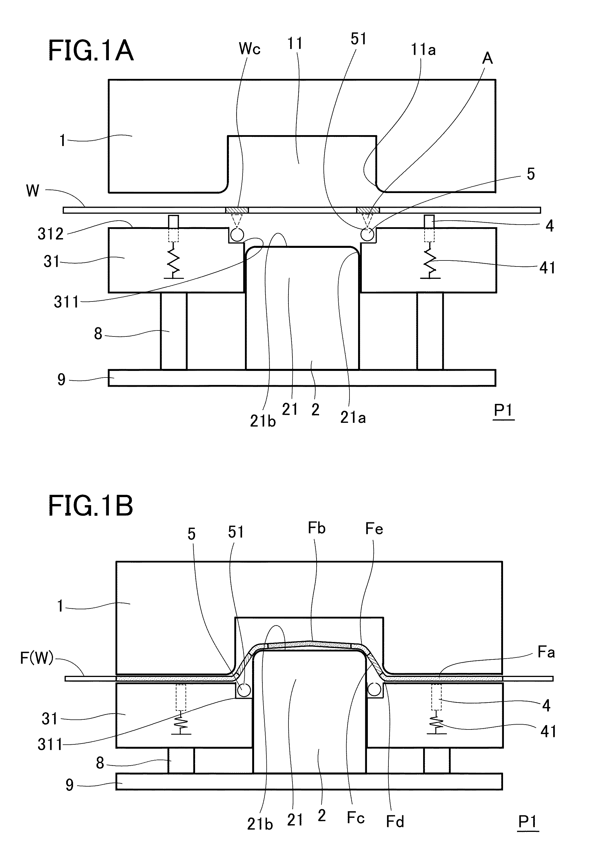
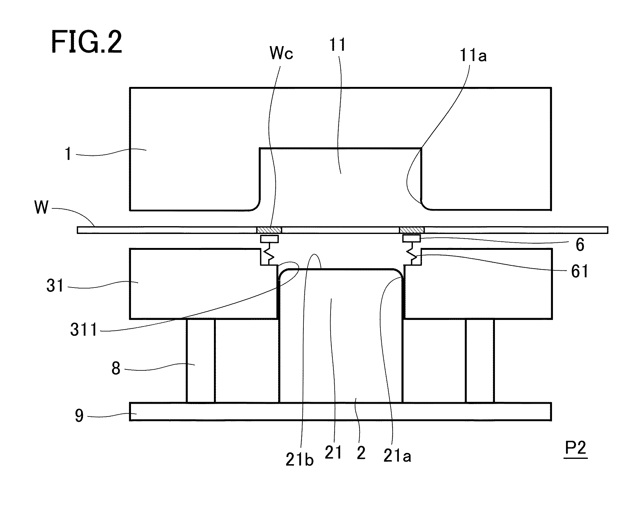
[0096]The above-described forming apparatus P1 and the forming apparatus P3 were used to actually form steel sheets W. Each specification of the prepared metal die at that time is as follows. The forming convex 21 of the punch 2 was designed to have: width of 70 mm; longitudinal straight line width of 70 mm; oval pillar-like shape having diameter of both-side semicircles of 70 mm; and shoulder part 21a having angled rounded radius (R) of 6 mm. The forming concave 11 of the die 1 was designed to have: width of 84 mm; longitudinal straight line width of 84 mm; oval cylinder-like shape having diameter of both-side semicircles of 84 mm; and angled curved part 11a having angled rounded radius (R) of 6 mm. The blank holders 31 and 33 were designed to have: width of 71 mm; longitudinal straight line width of 71 mm; and oval cylinder-like shape having diameter of both-side semicircles of 71 mm. In addition, above the inner circumference side of the blank holde...

example 2

(1) Suppression of Temperature Fall at Flange Region

[0103]First, using a forming apparatus (refer to FIG. 3A and FIG. 3B) without any cooling means for the bridge region Wc of the steel sheet W and any holder (such as holding pins 4) for the steel sheet W, hot press-forming was performed while interposing distance blocks D between the die 1 and the blank holder 31. At that time, the shape of the metal die used (forming concave of die 1 and forming convex of punch 2) and the composition of the steel sheet W, etc, were modified in some degree, but the hot press-forming was performed essentially according to Example 1.

[0104]While employing various heights (h) of the distance blocks D and repeating hot press-forming for steel sheets W of sheet thickness (t), the relationship was obtained between the amount of clearance formed between the die 1 and the blank holder 31 (c=h−t) and the maximum height of the press-formed product without occurrence of breakage (critical forming height, refer...


PUM

PropertyMeasurementUnit
Temperatureaaaaaaaaaa
Thicknessaaaaaaaaaa
Circumferenceaaaaaaaaaa

Abstract

A hot press-forming method includes a forming step that clamps a steel sheet heated to a temperature not less than an austenite transformation temperature and press-forms the steel sheet into a desired shape by causing a forming concave of a die and a convex of a punch to be close to each other. A formed portion has side and top portions that merge. The side portion rises up from an inner circumferential edge of a flange portion having been clamped by the die and the blank holder. A cooling step cools a region of the steel sheet after the heating step has been completed and before the forming step is completed. The particular region is along an inter-edge area formed between an opening circumferential edge of the forming concave and a top circumferential edge of the forming convex before the forming step is completed.

Description

TECHNICAL FIELD[0001]The present invention relates to a press-formed product obtained by hot press-forming of a steel sheet and also to a hot press-forming method and a hot press-forming apparatus which are suitable for production of the press-formed product.BACKGROUND ART[0002]Products obtained by press-forming (referred to as “press-formed products”) are heavily used in various fields, such as vehicle, home electronics, household furniture and general merchandise fields. A press-formed product can be obtained in general by expanding or drawing a metal sheet, which is clamped by a circumference edge portion of a die and a blank holder (referred also to as “anti-wrinkle holder”, etc), between a forming concave of the die and a forming convex of a punch so that the metal sheet is plastically deformed into a desired shape.[0003]By performing such press-forming, members having a complex shape can efficiently be mass-produced. However, when hot-press forming is employed to produce a cer...

Claims


Application Information

Patent Timeline
IPC IPC(8): B21D22/20C21D8/04C21D8/02
CPCB21D22/208C21D8/0247C21D2221/00C21D2211/008C21D8/0494C21D1/673Y10T428/12389B21D22/20B21D22/02B21D37/10
Inventor OTA, EIICHIMURATA, ATSUNOBUMATSUSHIMA, SATORU
Owner TOYOTA CENT RES & DEV LAB INC
Why Eureka
Try Eureka