
High speed pocket milling optimisation

a high-speed, pocket-sized technology, applied in the direction of instrumentation, program control, total factory control, etc., can solve the problems of reducing the efficiency of the milling process, ignoring the main drawbacks, and not sufficiently addressing the mentioned toolpath generation methods

Inactive Publication Date: 2014-10-02
ECOLE POLYTECHNIQUE FEDERALE DE LAUSANNE (EPFL)
View PDF1 Cites 35 Cited by
  • Summary
  • Abstract
  • Description
  • Claims
  • Application Information

AI Technical Summary

Benefits of technology

The present invention is a method for optimizing the cutting process in machine tool systems, particularly for high-speed milling of pockets. The method takes into account various factors such as machine tool constraints, cutting tool specifications, and toolpath generation. It uses a new genetic algorithm-based optimization method that minimizes variations in radial depth of cut and avoids sharp corners along the toolpath. The method allows for the automatic selection of cutting parameters and the optimization of milling time, reducing trial cutting tests, part verification, and energy consumption. It also reduces tool breakage, tool wear, and waste. The method includes two sub-methods: toolpath generation and cutting parameters optimization. The method has been tested and shown to be effective in reducing machining time and costs.

Problems solved by technology

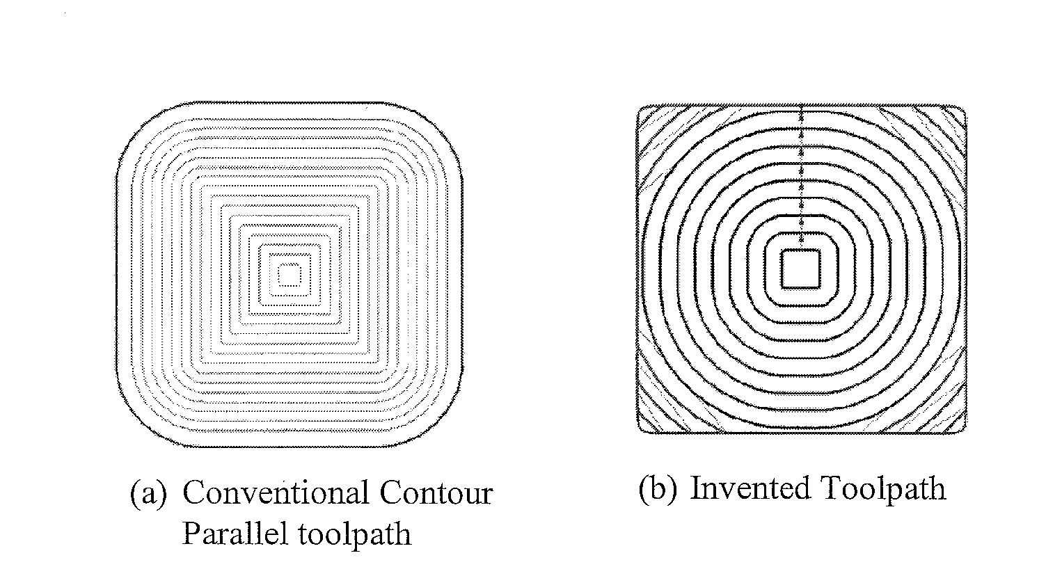
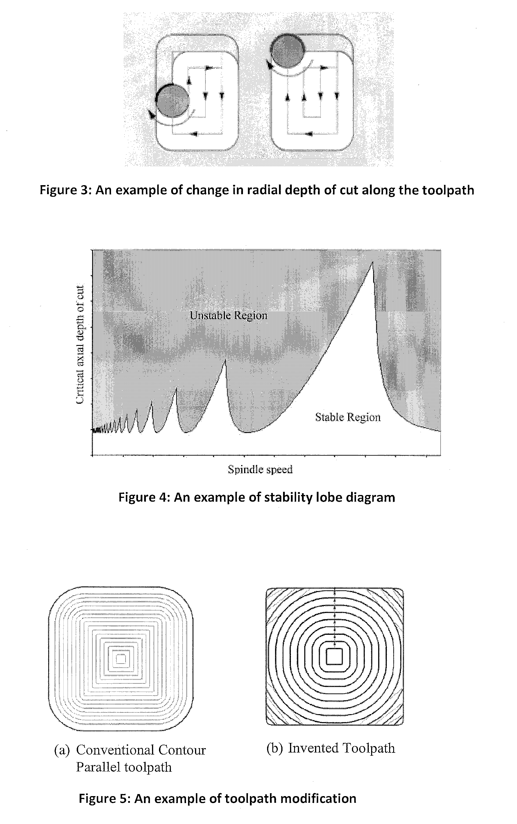
The generation of corners affect both machine tool kinematics (rapid change in feed rate) and process related aspect (sudden fluctuation in cutting force, vibration, fast wearing of cutting tool due to thermal fluctuation), while the restriction over stepover reduces the efficiency of milling process drastically.
It can be concluded that the above-mentioned toolpath generation methods although improving toolpath for milling process, do not sufficiently address the main drawbacks specified in point (i) and point (ii) mentioned above.
Due to the lack of knowledge about machine-tool dynamic behaviour these guidelines do not ensure the selection of optimal or near optimal cutting parameters.
There are numerous methods to solve optimization problems but there is no efficient all-purpose optimization method available.
Some methods produce accurate solutions by making rigorous computations which is not computationally economical in terms of time and cost.
Some models develop solutions closer to the optimum in a fast manner Therefore, a compromise between the high accuracy of a rigorous solution and lower accuracy of a computationally efficient method has to be made.
2007] has developed GA optimization algorithm to maximize material removal rate while considering the stability of the milling process but their technique is limited in terms of design variables.
It is obvious that real optimal cutting parameters cannot be achieved without considering all cutting parameters (spindle speed, axial depth of cut, radial depth of cut and feed rate), constraints and toolpath simultaneously.

Method used


Image

  • High speed pocket milling optimisation
  • High speed pocket milling optimisation
  • High speed pocket milling optimisation

Examples


example

[0176]The complete method is illustrated with a simple example:

[0177]Various Inputs:

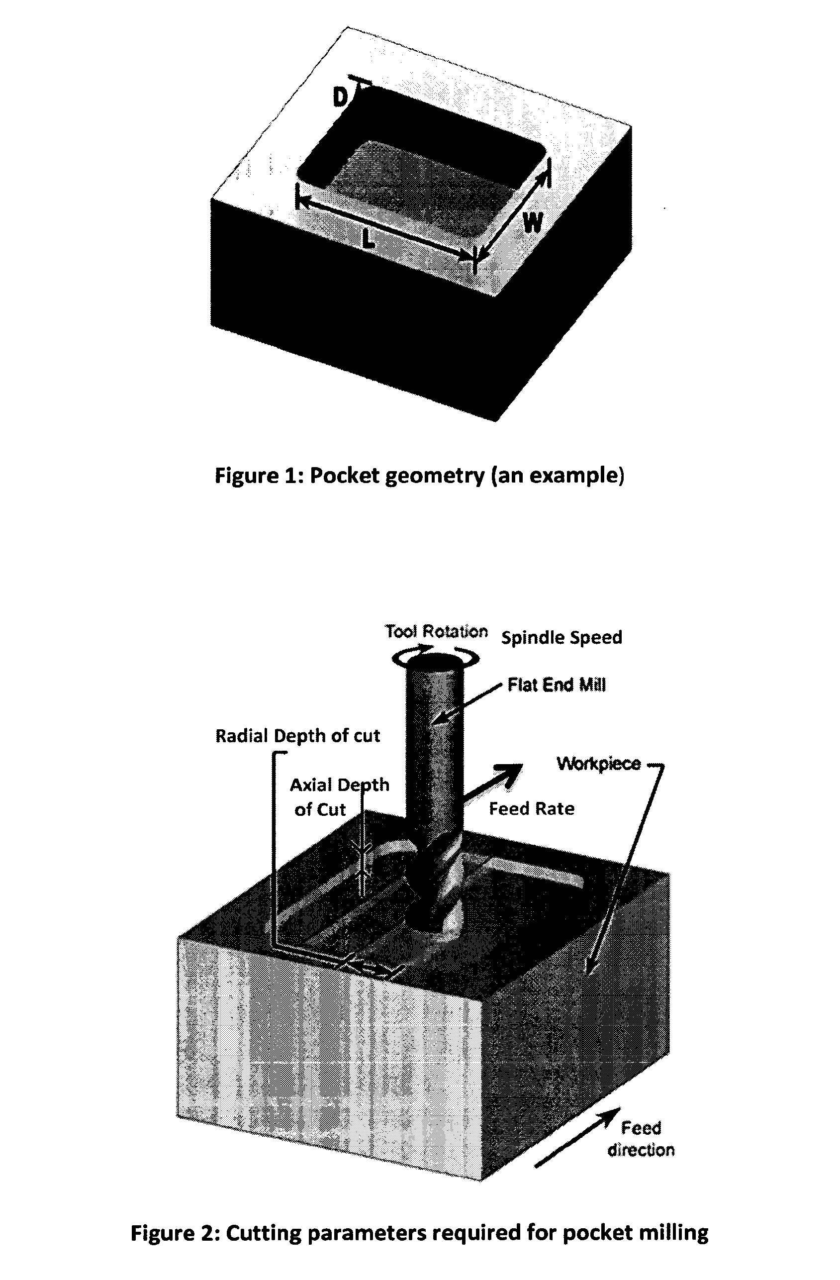
[0178]1. An example pocket dimensions are presented in FIG. 22.

[0179]2. The specifications of the cutting tool are given in Table 1.

TABLE 1An example of cutting tool specificationsCuttingDiameterHelix AngleRake AngleLengthTotal Length(mm)(deg)(mm)Flutes(mm)(mm)16402539232

[0180]3. For a combination of the work piece material and cutting tool specifications cutting force coefficients are given in Table 2.

TABLE 2An example of cutting force coefficientsKtcKrcKacKteKreKae(N / mm2)(N / mm2)(N / mm2)(N / mm)(N / mm)(N / mm)6818621812192

[0181]Where Ktc, Krc and Kac are the cutting coefficients contributed by the shearing action whereas Kte, Kre and Kae are the edge coefficients in tangential, radial and axial directions respectively (see reference Altintas 2000).

[0182]4. Frequency Response Function (FRF) of machine tool / spindle / tool holder / cutting tool system at tool tip in the feed and normal to feed direction is gener...


PUM


Abstract

The invention relates to a method of toolpath generation and cutting parameters optimization for high speed milling of a convex pocket, wherein said method comprises a first sub-method of generating a toolpath and a second sub-method of generating optimized chatfree cutting parameters using a genetic algorithm wherein the first sub-method generates milling toolpaths that minimize the radial depth of cut variations as well as the curvature change variations while avoiding leftover material at the corners, wherein said toolpaths automatically avoid self-intersecting features encountered during the offsetting of pocket boundary such that the said toolpaths result in reduction in milling time for a given maximum acceptable radial depth of cut and wherein said second sub-method allows the free choice of cutting parameters and optimizes the milling time and wherein the optimization method incorporates relevant milling constraints as milling stability constraint, cutting forces, machine-tool and cutting tool capabilities.

Description

RELATED APPLICATION[0001]The present application claims priority to earlier EP application No 11154120.7 filed on Feb. 11, 2011 in the name of the same applicant, the content of which is incorporated in its entirety in the present application.BACKGROUND OF THE INVENTION[0002]The introduction of high-speed machining (HSM) in the current practice of milling promises great benefits in productivity and part quality. However, the optimal use of this relatively new technology is sometimes hampered by chatter vibrations which may damage the tool, the work piece or even may cause wear and tear on the spindle. Although a lot of progress has been performed in the past decades in studying and better understanding of the chatter problem and the factors that influence it, there is still a practical need to bring to the shop floor some tools that will assist process planners in their part programming to avoid chatter vibrations while using the full potential of the machine tool system.[0003]Europ...

Claims


Application Information

Patent Timeline
Patent Type & Authority Applications(United States)
IPC IPC(8): G05B19/402
CPCG05B19/402G05B19/40937G05B2219/36214G05B2219/50329G06F30/23G06F30/20Y02P90/02G05B2219/40523G05B2219/34105G05B2219/39358
Inventor AGGARWAL, SAURABHDHANIK, SANDEEPXIROUCHAKIS, PAUL
Owner ECOLE POLYTECHNIQUE FEDERALE DE LAUSANNE (EPFL)
Learn More