
Control device for vehicle drive device

a technology of control device and drive device, which is applied in the direction of electric devices, process and machine control, instruments, etc., can solve the problems of affecting the smooth operation of the input-side rotating member, the inability to ensure the comfortable traveling performance, and the rapid increase of the torque that is transferred to the wheels. , to achieve the effect of smooth execution and comfortable traveling

Active Publication Date: 2014-10-02
AISIN AW CO LTD
View PDF3 Cites 10 Cited by
  • Summary
  • Abstract
  • Description
  • Claims
  • Application Information

AI Technical Summary

Benefits of technology

The patent describes a configuration for a vehicle transmission that allows for smooth and quick starting and shifting without causing discomfort or stopping the vehicle. This is achieved by appropriately deciding on the shift engagement device based on the vehicle's speed and the speed at which the driver intends to engage the shifting mechanism. The special engagement device is used when the vehicle speed is relatively low, while the normally disengaged engagement device is used when the vehicle speed is higher. The use of both engagement devices ensures that the vehicle can transition smoothly to the desired shifting speed and provides a comfortable traveling performance. The patent also describes setting a determination speed to ensure a certain amount of margin up to the end point of the shifting to the special shift speed after starting the internal combustion engine. This ensures that the speed change mechanism rotational speed does not increase too much, allowing for effective comfortable traveling performance.

Problems solved by technology

As a result, the shift control is immediately terminated, and subsequently the rotational speed of the input-side rotating member decreases (see FIG. 16 of the present application), whereby comfortable traveling performance may not be ensured.
In this case, however, the torque that is transferred to the wheels rapidly increases accordingly, whereby comfortable traveling performance may not be ensured.

Method used


Image

  • Control device for vehicle drive device
  • Control device for vehicle drive device
  • Control device for vehicle drive device

Examples


first assumed example

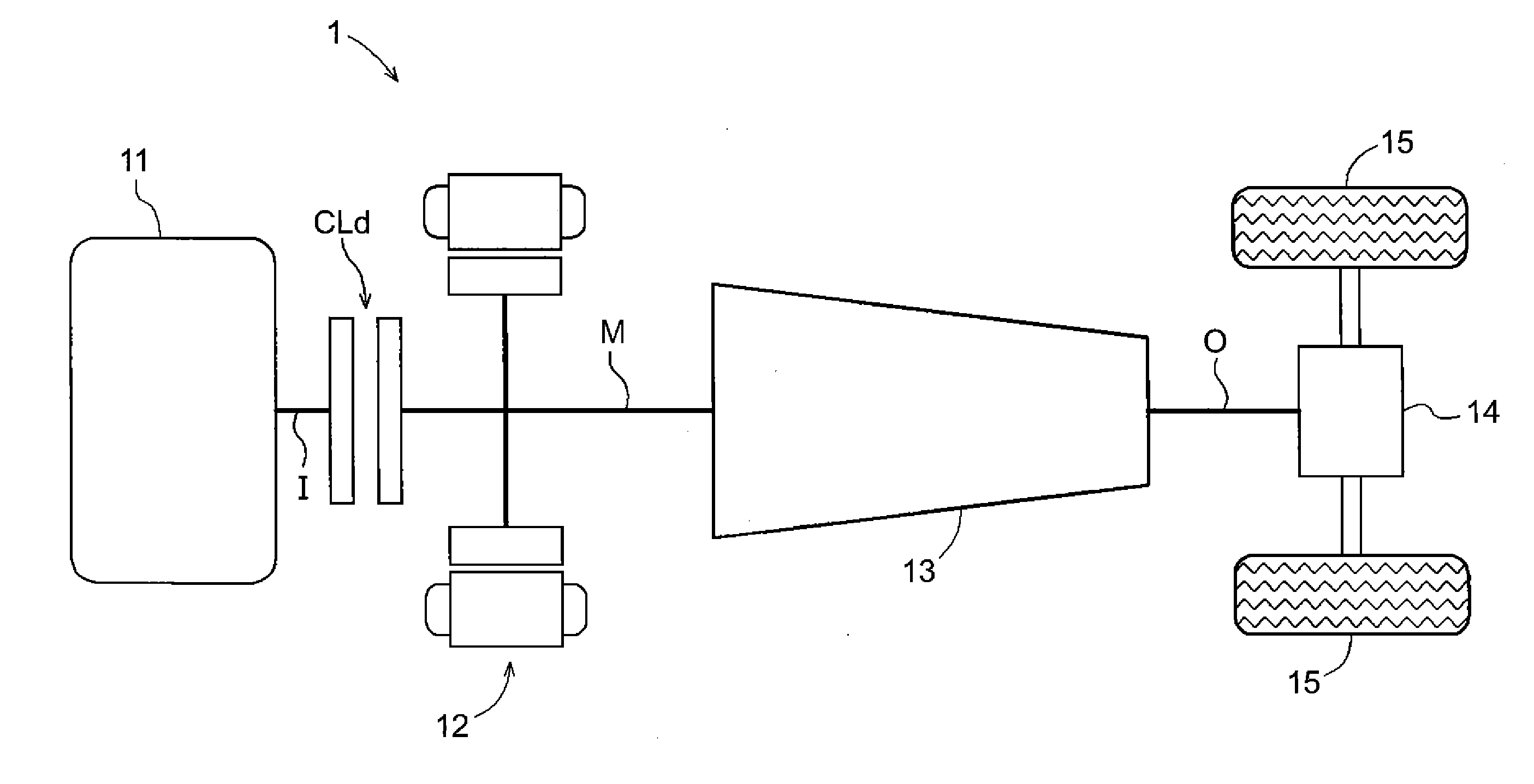
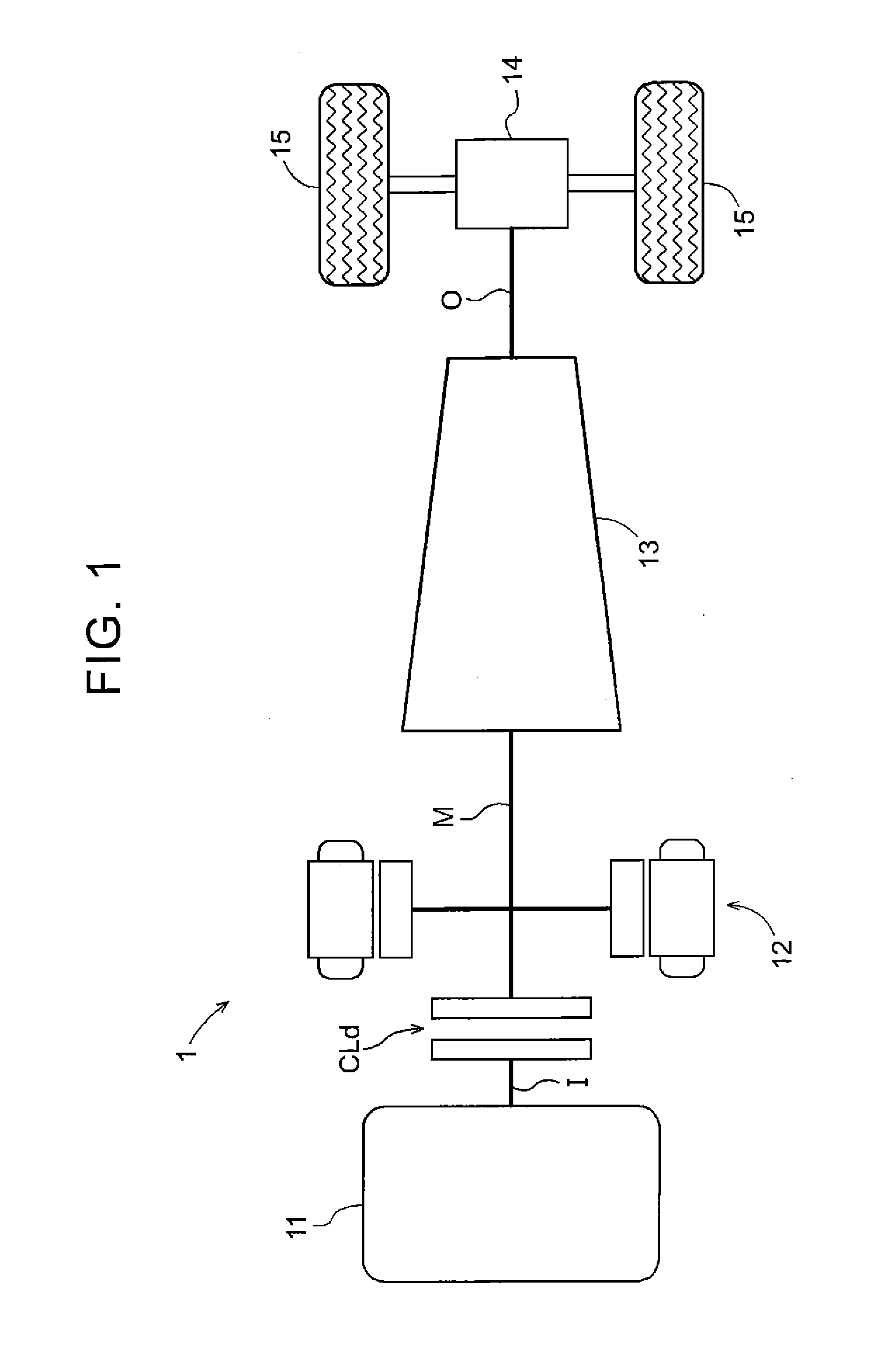
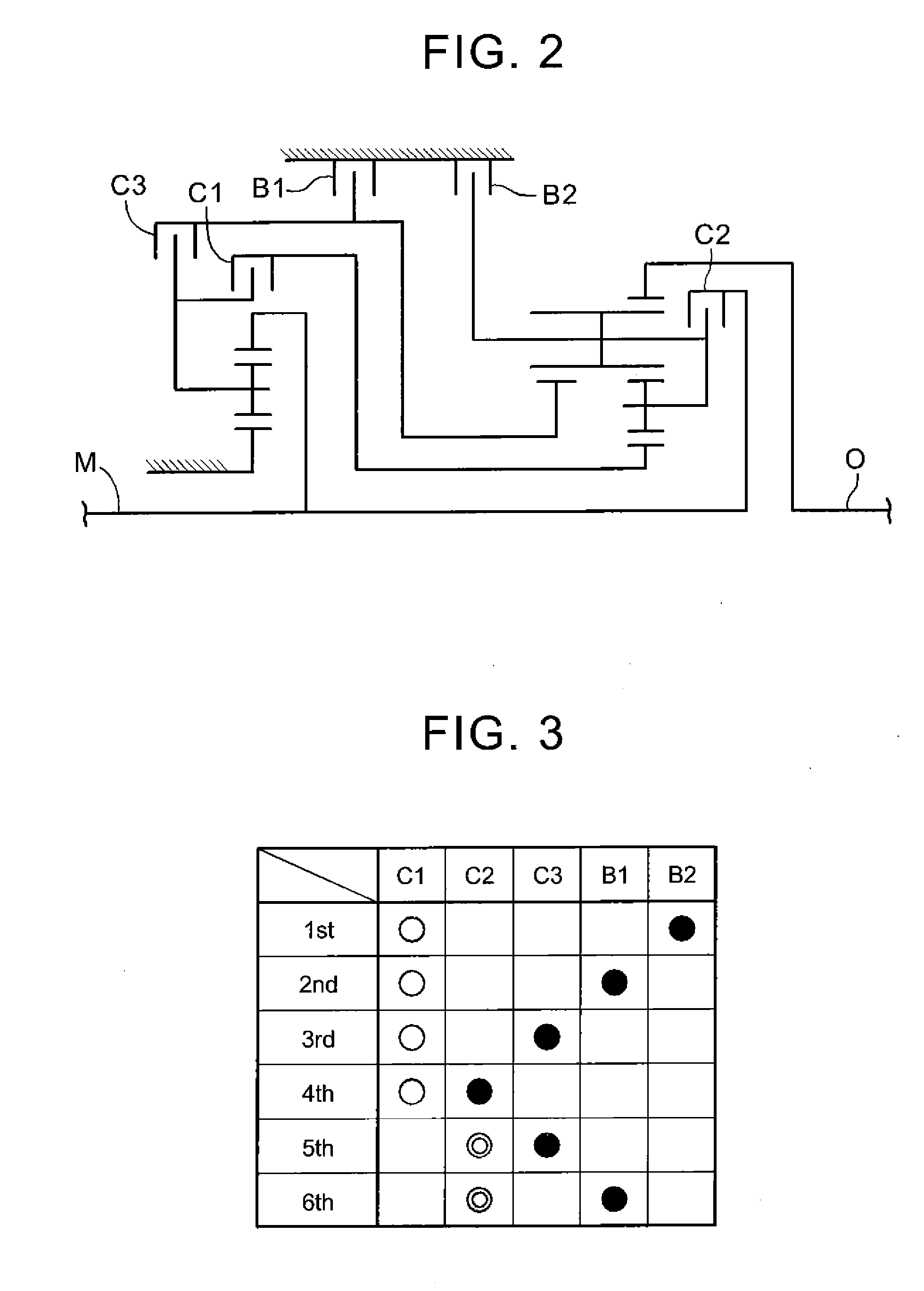
[0063]In the present embodiment, it is first assumed that the vehicle is traveling in the electric drive mode with the fifth speed being formed in the speed change mechanism 13. In the present embodiment, as shown in FIGS. 3 and 7, the fifth speed is formed with both a second clutch C2 and a third clutch C3 being in the direct-coupling engaged state and the other shift engagement devices being in the disengaged state. It is herein assumed that in this state, an internal combustion engine start request and a shift request (in this example, a downshift request as a request for shift to a shift speed with a relatively high speed ratio) are received at substantially the same time.

[0064]In this assumed example, the fifth speed that has been formed at the start of the internal combustion engine start control and the start slip control associated therewith corresponds to the “reference shift speed” and the “first shift speed” in the present invention. The fourth speed that is one shift spe...

second assumed example

[0081]It is now assumed that the vehicle is traveling in the electric drive mode with the sixth speed being formed in the speed change mechanism 13. In the present embodiment, as shown in FIGS. 3 and 10, the sixth speed is formed with both the second clutch C2 and the first brake B1 being in the direct-coupling engaged state and the other shift engagement devices being in the disengaged state. It is herein assumed that in this state, an internal combustion engine start control request and a shift request (in this example, a downshift request) are received substantially at the same time.

[0082]In this assumed example, the sixth speed formed at the time the internal combustion engine start control and the start slip control associated therewith are started corresponds to the “reference shift speed” and the “first shift speed” in the present invention. The fifth speed that is one shift speed lower in this assumed example than the sixth speed corresponds to the “specific shift speed” in ...


PUM


Abstract

A control device for a vehicle drive device. A start control section executes internal combustion engine start control. A start slip control section executes start slip control of bringing one of the plurality of shift engagement devices into a slip engaged state. An intended engagement device deciding section that decides as an intended engagement device, based on a set determination speed. The intended engagement device deciding section decides as the intended engagement device a special engagement device that is the shift engagement device having been in the direct-coupling engaged state in order to form the reference shift speed, and that is disengaged when a transition is made to a special shift speed on an opposite side of the specific shift speed from the reference shift speed in order of speed ratios of the plurality of shift speeds.

Description

TECHNICAL FIELD[0001]The present invention relates to control devices that control a vehicle drive device in which a disconnecting engagement device, a rotating electrical machine, and a speed change mechanism are provided in this order from an internal combustion engine toward wheels on a power transmission path connecting the internal combustion engine and the wheels.BACKGROUND ART[0002]A device described in Japanese Patent Application Publication No. 2008-207643 (JP 2008-207643 A) (Patent Document 1) is already known as such a control device that controls a vehicle drive device as described above. The names of members in Patent Document 1 that correspond to members in the present invention are referred to in parentheses “[ ]” in the description of this section “BACKGROUND ART.” In this control device, one of a plurality of shift engagement devices [fastening elements] included in the speed change mechanism [automatic transmission AT] is brought into a slip engaged state upon a ch...

Claims


Application Information

Patent Timeline
Patent Type & Authority Applications(United States)
IPC IPC(8): B60W30/19B60W10/06B60W10/02B60W20/00B60L50/16
CPCB60W10/115Y10S903/93B60K6/48B60K6/547B60L11/14B60W10/06B60W10/10B60W20/00F16H61/02F16H61/686F16H63/50Y02T10/6221Y02T10/7077Y02T10/642B60L3/106B60L2240/12B60L2240/423B60L2240/465B60W10/02B60W20/30B60W30/19B60L50/16B60Y2200/92B60Y2300/18083F16H61/04Y02T10/62Y02T10/64Y02T10/7072Y02T10/70
Inventor TSUDA, KOHEITAJIMA, YOICHI
Owner AISIN AW CO LTD
Learn More