Cutting insert, cutting tool, and method of producing machined product using the same

a cutting tool and cutting insert technology, applied in the direction of manufacturing tools, shaping cutters, metal working devices, etc., can solve the problems of chip extending without being curled and divided, and damage the machined surface of the workpiece, and achieve excellent chip discharge performance and stable curling

Active Publication Date: 2014-10-09
KYOCERA CORP
View PDF10 Cites 48 Cited by
  • Summary
  • Abstract
  • Description
  • Claims
  • Application Information

AI Technical Summary

Benefits of technology

[0009]With the cutting insert according to the embodiment of the present invention, the upper surface sequentially includes the first rake surface and the second rake surface. The first rake surface is located along the cutting edge and is inclined toward the lower surface as going inward from the cutting edge at the first rake angle on the basis of the perpendicular plane perpendicular to the central axis extending between the upper surface and the lower surface. The second rake surface is located more inward than the first rake surface and is inclined toward the lower surface at the second rake angle different from the first rake angle on the basis of the perpendicular plane. The intersecting part of the first rake surface and the second rake surface includes the protruded part located at the highest position in the region of the intersecting part extending along the second side surface. Therefore, even under the cutting conditions that the corner cutting edge and the minor cutting edge are used mainly and the depth of cut is relatively small, generated chips can be stably curled by the high protruded part located in the region of the intersecting part extending along the second side surface, thereby exhibiting the excellent chip discharge performance.

Problems solved by technology

However, when the cutting plate of Japanese Unexamined Patent Publication No. 2004-314301 is used, for example, under cutting conditions that the depth of cut is small, such as in the case of finish cut, there is a risk that chips extending without being curled and divided may damage a machined surface of a workpiece.

Method used


Image

  • Cutting insert, cutting tool, and method of producing machined product using the same
  • Cutting insert, cutting tool, and method of producing machined product using the same
  • Cutting insert, cutting tool, and method of producing machined product using the same

Examples


Embodiment Construction

[0022]A cutting insert (hereinafter generally referred to as an “insert”) according to an embodiment of the present invention is described in detail below with reference to FIGS. 1 to 7.

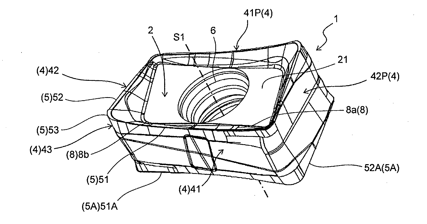
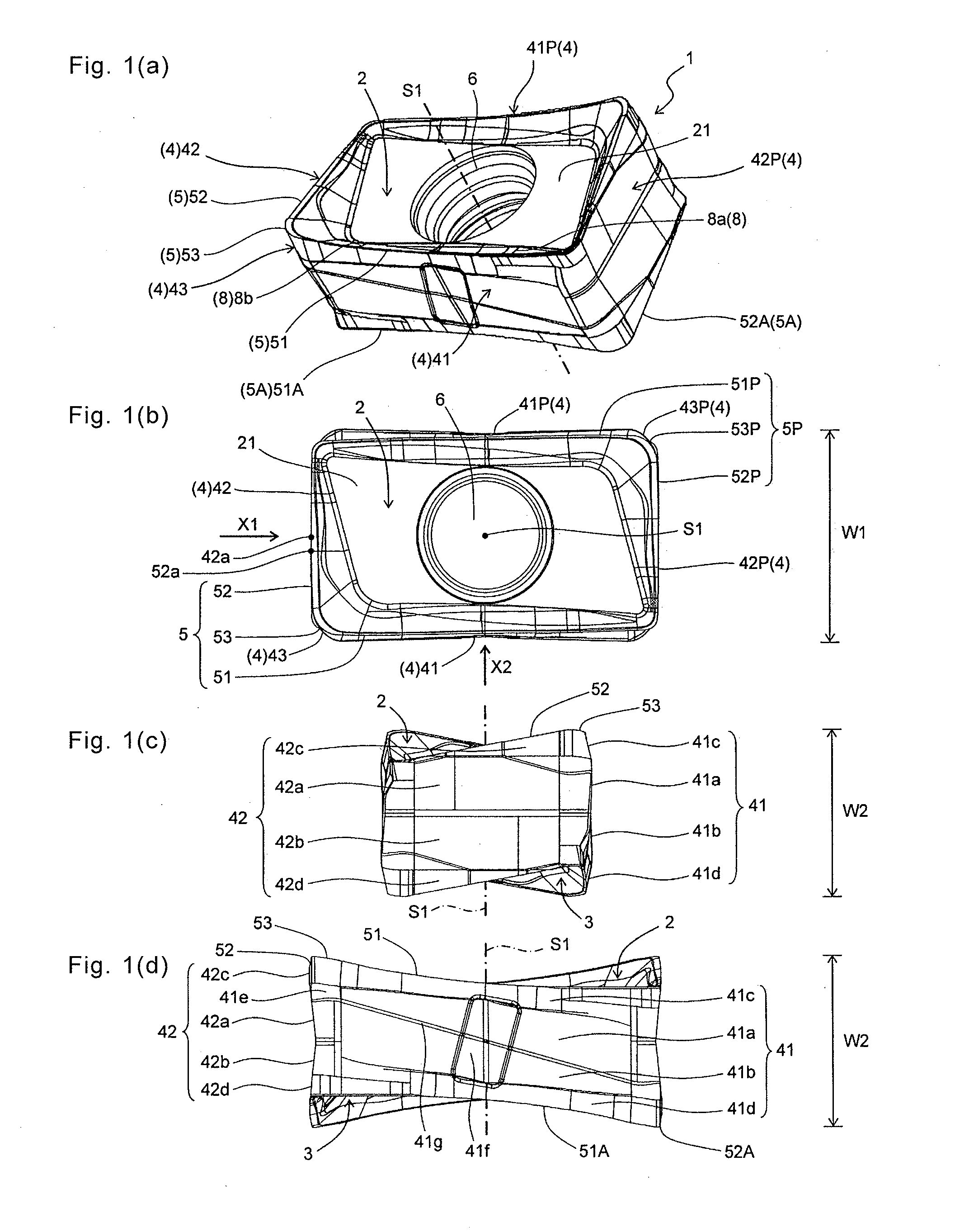
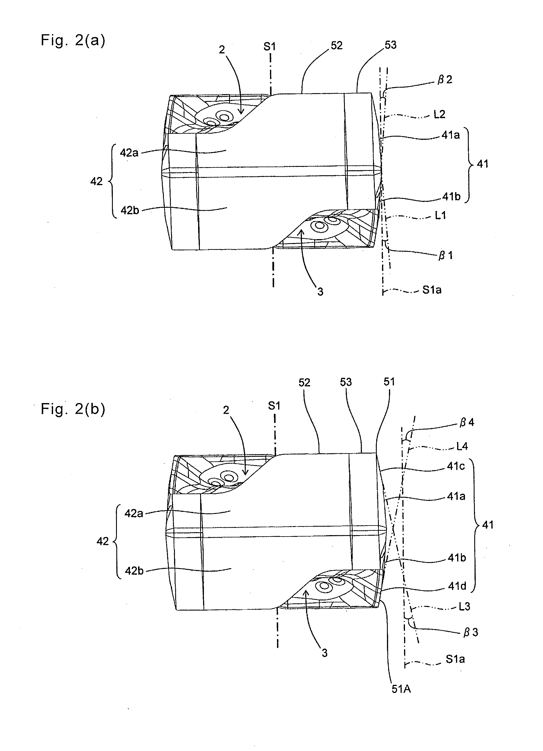
[0023]As shown in FIG. 1, the insert 1 of the present embodiment generally includes an upper surface 2, a lower surface 3, a side surface 4 connected to each of the upper surface 2 and the lower surface 3, a through hole 6 extending between the upper surface 2 and the lower surface 3, and a cutting edge 5 located at an intersecting part of the upper surface 2 and the side surface 4. The upper surface 2 includes a rake surface 8 and a flat surface 21. The side surface 4 includes a first side surface 41, a corner side surface 43, and a second side surface 42. The cutting edge 5 includes a major cutting edge 51, a corner cutting edge 53, and a minor cutting edge 52. The individual components of the insert 1 are sequentially described below.

[0024]As shown in FIG. 1(b), the insert 1 has an approximately q...


PUM


Abstract

A cutting insert comprises an upper surface sequentially including a first and second rake surface. The first rake surface is inclined toward the lower surface, going inward from the cutting edge at a first rake angle on a basis of a perpendicular plane perpendicular to a central axis extending between the upper surface and a lower surface. The second rake surface, located more inward than the first rake surface, is inclined toward the lower surface at a second rake angle different from the first rake angle on the basis of the perpendicular plane. An intersecting part of the first rake surface and the second rake surface includes a protruded part located at a highest position in a region of the intersecting part along the second side surface. A cutting tool with the cutting insert, and a method of producing a machined product using the cutting tool are provided.

Description

TECHNICAL FIELD[0001]The present invention relates to a cutting insert, a cutting tool, and a method of producing a machined product using the same.BACKGROUND ART[0002]Conventionally, a configuration in which a rake surface, a step part, and a seating surface are sequentially located inwardly from a corner cutting edge has been proposed as a cutting plate for use in a face milling process (for example, refer to Japanese Unexamined Patent Publication No. 2004-314301).[0003]However, when the cutting plate of Japanese Unexamined Patent Publication No. 2004-314301 is used, for example, under cutting conditions that the depth of cut is small, such as in the case of finish cut, there is a risk that chips extending without being curled and divided may damage a machined surface of a workpiece.[0004]Hence, there is a need for an insert with excellent chip discharge performance in order to suppress quality deterioration of the machined surface of the workpiece due to the chips as described ab...

Claims


Application Information

Patent Timeline
Patent Type & Authority Applications(United States)
IPC IPC(8): B23C5/06
CPCB23C5/06B23C5/109B23C2200/125B23C2200/085B23C2200/0494B23C2210/045B23C2210/0457B23C5/202Y10T407/23Y10T407/22Y10T83/04B23C2200/284
Inventor ISHI, HIROHISA
Owner KYOCERA CORP
Why Eureka
Try Eureka