
Method of Delivering, Storing, Unloading, and Using Proppant at a Well Site

a well site and proppant technology, applied in the field of storage containers, can solve the problems of increasing the demand for proppant, reducing the service life of the proppant,

Active Publication Date: 2014-10-09
SANDBOX ENTERPRISES LLC
View PDF6 Cites 17 Cited by
  • Summary
  • Abstract
  • Description
  • Claims
  • Application Information

AI Technical Summary

Benefits of technology

The present invention is a container for transporting and storing proppant, which is used in fracturing sites. The container has a box with a bottom and sidewalls, and a gate that can be opened and closed. The container can be positioned on a support structure and has a conveyor system to move the proppant from the container to a desired location. The invention also includes a system for discharging the proppant from the container onto the conveyor system. The container is designed to be easily moved and can be positioned on a train or vehicle for transport. The invention allows for efficient and safe delivery of proppant to fracturing sites.

Problems solved by technology

With the rise of hydraulic fracturing over the past decade, there is a steep climb in proppant demand.
Global supplies are currently tight.
However, it may break down or crush more readily under stress due to the relatively fewer grain-to-grain contact points to bear the stress often incurred in deep oil- and gas-bearing formations.
Typically, in any hydraulic fracturing operation, a large amount of such proppant is required.
Typically, it has been difficult to effectively store the proppant at the fracturing sites.
Additionally, it has been found to be rather difficult to effectively transport the proppant to the desired location.
Under such circumstances, the proppant is often exposed to adverse weather conditions.
This will effectively degrade the quality of the proppant during its storage.
Additionally, the maintenance of proppant in containers at the hydraulic fracturing site requires a large capital investment in storage facilities.
With the development and acceptance of the well stimulation methodology known as “hydraulic fracturing”, a unique logistics challenge has been created in delivering the massive quantities of proppant from domestic sand mines to the wellhead.
This logistics challenge affects every stakeholder up-and-down the logistics chain.
This makes the process subject to a myriad of problems that disrupt the efficient flow of proppant to the wellhead.
The result of utilizing the current method is the expenditure of hundreds of millions of dollars in largely unnecessary logistics costs.
Most of the recent mines that have come on-line, or are in varying stages of development, have limited transportation infrastructure to support the export of sand from the sand-pit.
Along with rail-track, these companies are also investing in expensive vertical silo storage facilities to store thousands of tons of proppant.
The sand mines are unable to effectively ship proppant to the shale regions without equal fluid trans-loading and storage facilities on the receiving end of the logistics chain.
This results in lost revenue and productivity for the mine owner and higher prices for proppant buyers in the destination region.
Recently, the railroads have seen the allocated fleet of hopper cars being stranded at those destinations where there is no cost-effective storage option to efficiently off-load those cars.
Consequently, there has been a significant opportunity cost that the railroads have been forced to pay.
Limited storage at trans-loading facilities has severely limited many of the current facilities' ability to operate efficiently.
This requires an intense coordination effort on the part of the trans-loader as well as the trucking community.
As such, the trans-loader is not able to fully realize the utilization of conveying and other material handling equipment.
The throughput of these trans-loading terminals severely reduces costing of the terminal meaningful revenue.
Additionally, optimal trans-load terminal locations are immobile and not able to move from one area of the shale pay to another.
A potential loss of the investment in such immobile silos can often scare investment capital away from these types of future projects so as to further exacerbate the logistics chain problem.
The lack of efficient trans-load and storage facilities in shale regions have taken a heavy toll on the efficiencies of trucking fleets.
While trucking companies have typically charged demurrage fees to compensate for the waiting time and lost productivity, those types of charges are under significant resistance from the customer base.
When trucking companies are required to wait in line to be loaded, or wait at a well-site to be unloaded, the number of turns that the equipment can make in a day is severely limited.
Rather than turning two or three loads in a single day, the trucks more typically make one trip per day, and very commonly may make one delivery every two or three days, This lack of efficient fleet utilization results in the trucking, company having to buy more equipment and hire more drivers to move the same amount of material than would be necessary.
This is the result of inefficient trans-load facilities and pneumatic (bulk) truck deliveries.
The service company cannot frac a well if it does not have a supply of proppant.
It is widely known that the problems surrounding the efficient delivery of proppant to the well-site is one of the primary challenges to the service companies in successfully completing a frac job.
Pressure pumps, coiled tubing and other well stimulation equipment, often site idle due to the lack of required proppant at the well-site, “Screening-Out” or running out of proppant is very common at well locations due to the lack of control over what is happening up-stream in the proppant logistics chain.
This results in lower profit margins to the service company.
In doing so, many of these companies have been forced to source material and employ very expensive logistics options in order to survive.
This has resulted in above-market pricing in order to complete wells.
There is also as risk of losing out on otherwise viable hydraulic fracturing contracts.
Exploration and production companies need to pass on the overall increased cost of production.
The specialized equipment that was required to lift the full containers was so heavy and large that it would have to be disassembled into several pieces before moving from one location to another.
This created some limitations on the flexibility that such equipment lent to the containerized process.
Currently, many proppant buyers are subject to inaccurate volume reporting from trans-loading facilities.
As such, they May not be certain that the proppant being delivered to the well-site is, in fact, of the quality and grade that they have purchased.
However, it did have several limitations.
For example, the twenty-foot ISO container, while capable of handling ninety thousand pounds of proppant, could not be transported legally over a public road.
Since proppant is divisible, the law does not allow for heavy or over-weight loads.
When analyzing the angle of repose of proppant poured into a twenty-foot ISO container, it was evident that much of the volume of such a container was void.
Specifically, the upper ends of twenty-foot ISO container could not be utilized without somehow manipulating or tilting the container as it was filled by a conveyor.
Moreover, when emptying the container, by way of the original bottom hatch, the proppant would pour directly out of the bottom and leave a significant amount of material sitting on the floor of the container.

Method used


Image

  • Method of Delivering, Storing, Unloading, and Using Proppant at a Well Site
  • Method of Delivering, Storing, Unloading, and Using Proppant at a Well Site
  • Method of Delivering, Storing, Unloading, and Using Proppant at a Well Site

Examples


Embodiment Construction

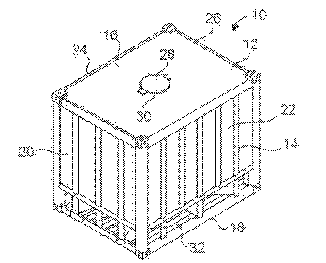
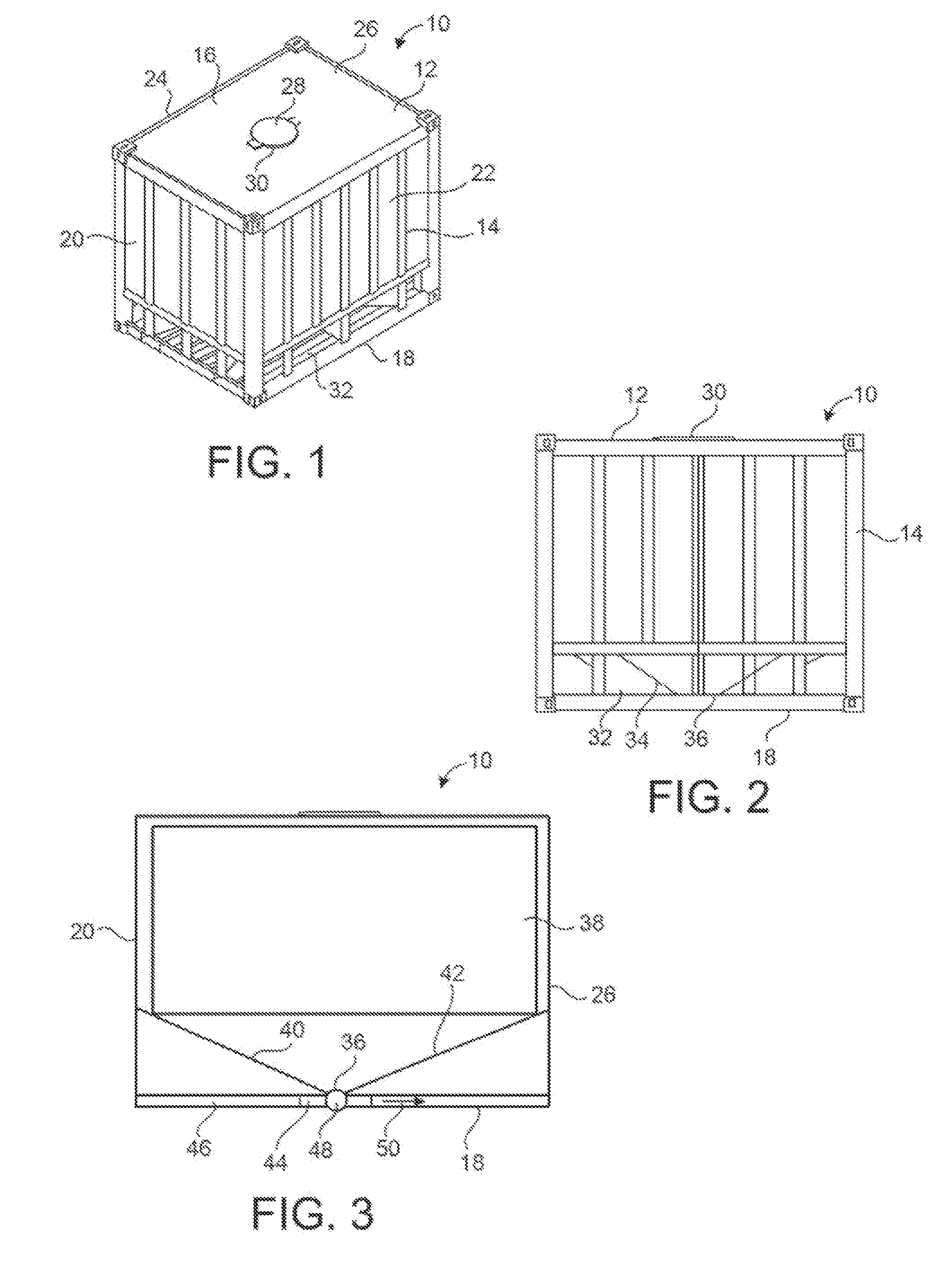
[0063]Referring to FIG. 1, there is shown the container 10 in accordance with the preferred embodiment of the present invention. The container 10 is in the nature of a box 12 having an exterior frame 14. The box 12 includes a top 16, a bottom 18, an end wall 20 and a side wall 22. The side wall 24 is opposite to the side wall 22. There also an end wall 26 that is opposite to that of end will 20. An inlet 28 is formed through the top 16 of the box 12. A hatch 30 is removably or hingedly affixed over the inlet 28 so as to allow proppant to be introduced into the interior volume of the container 10.

[0064]In FIG. 1, it can be seen that the frame 14 extends generally around the exterior of the end walls 20 and 26 and over the side walls 22 and 24. As such as will be described hereinafter, there is a funnel-shaped bottom of the container that has exterior surfaces exposed through the frame 14. During the course of international shipment, it is advantageous to avoid closed spaces within su...


PUM


Abstract

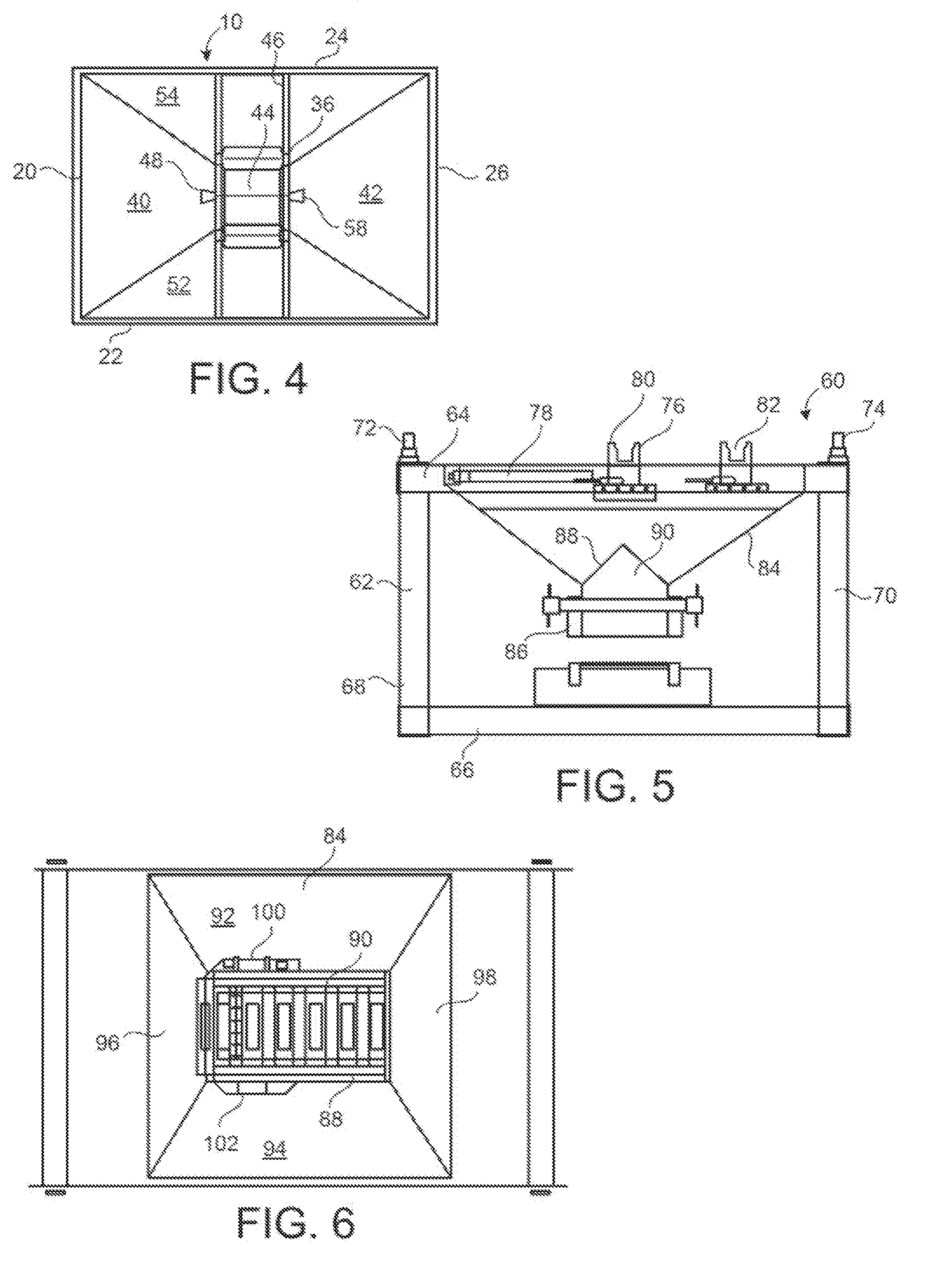
A proppant discharge system has a container with an outlet formed at a bottom thereof and a gate slidably affixed at the outlet so as to be movable between a first position covering the outlet to second position opening the outlet, and a support structure having an actuator thereon. The container is removably positioned on the top surface of the support structure. The actuator is engageable with gate so as to move the gate from the first position to the second position. A conveyor underlies the container so as to receive proppant as discharged from the container through the outlet. The container is a ten foot ISO container.

Description

RELATED APPLICATIONS[0001]This application is a continuation of U.S. patent application Ser. No. 13 / 628,702, filed Sep. 27, 2012, which is a continuation-in-part of U.S. patent application Ser. No. 13 / 555,635, filed Jul. 23, 2012, all of which are incorporated herein by reference in their entireties.BACKGROUND[0002]1. Field of the Invention[0003]The present invention relates to storage containers. More particularly, the present invention relates to proppant discharge systems wherein proppant can be discharged from the storage container. Additionally, the present invention relates to a process for providing proppant to a well site by the transport and delivery of the proppant containers.[0004]2. Description of Related Art[0005]Hydraulic fracturing is the propagation of fractions in a rock layer caused by the presence of pressurized fluid. Hydraulic fractures may form naturally, in the case of veins or dikes, or may be man-made in order to release petroleum, natural gas, coal seam gas...

Claims


Application Information

Patent Timeline
Patent Type & Authority Applications(United States)
IPC IPC(8): B65D88/30
CPCB65G65/40B60P1/56B65D90/587B65D88/30B65D88/26B65D88/38B65G65/42B65D83/06B65D7/00B65D88/121B65D88/129B65D88/32B65D88/54B65D90/58B65D2231/008B65D2547/04B65D2588/12B65D2590/664B65D88/02B65D88/28B65D90/54B65G65/30B65G2201/042B65G2814/0319B65D88/12B65D90/20B65D88/542B65D90/66B65G2814/032B65D88/022
Inventor OREN, JOHNOREN, JOSHUA
Owner SANDBOX ENTERPRISES LLC
Learn More