

Stretchable electric device and manufacturing method thereof
a technology of electric devices and stretchable materials, applied in the direction of flexible printed circuits, circuit bendability/stretchability, printed circuit aspects, etc., can solve the problems of limited stretchability of stretchable electric devices, difficult to apply a large area and secure reliability, and limitations of conductive stretchable materials, etc., to achieve the effect of convenient formation
- Summary
- Abstract
- Description
- Claims
- Application Information
AI Technical Summary
Benefits of technology
Problems solved by technology
Method used
Image

Examples
first embodiment
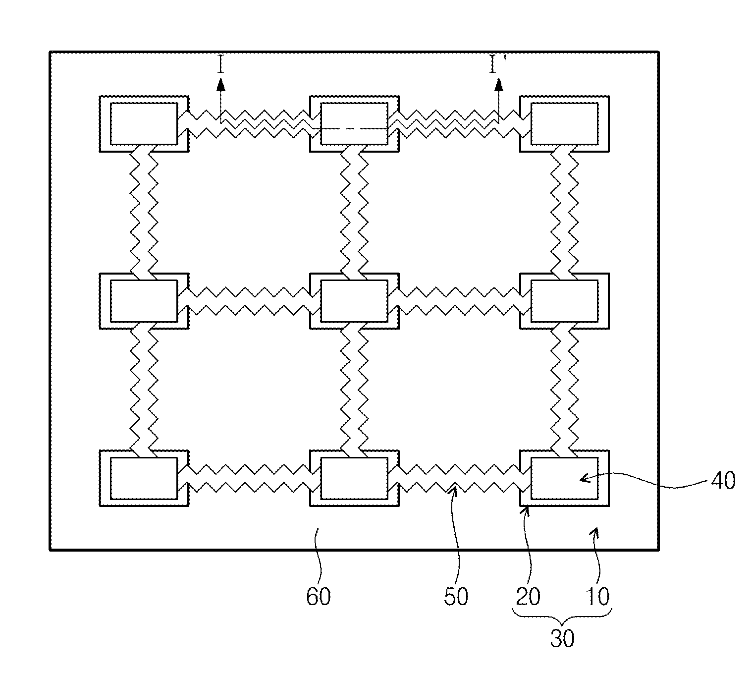
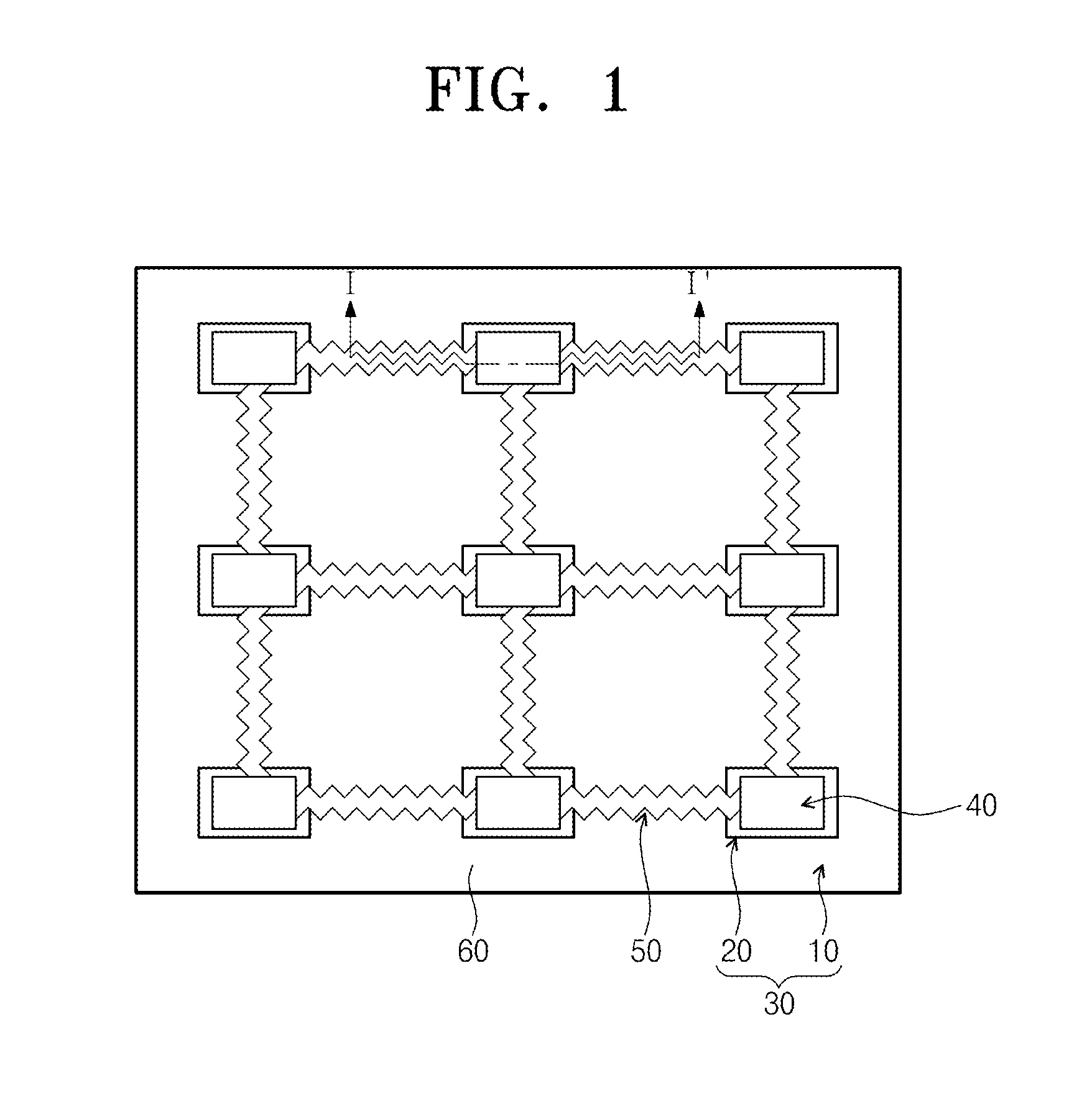
[0038]FIG. 1 is a plan view of a stretchable electric circuit according to the inventive concept. FIG. 2 is a cross-sectional view taken along line I-I′ of FIG. 1.
[0039]Referring to FIGS. 1 and 2, a stretchable electric circuit according to the first embodiment of the inventive concept may include a stretchable substrate 30, electric devices 40, corrugated wires 50, and a stretchable protection layer 60.
[0040]The stretchable substrate 30 may include a low-stiffness body 10 and high-stiffness blocks 20. The low-stiffness body 10 may have a first corrugated surface 12. The first corrugated surface 12 may be a roughness top surface of the low-stiffness body 10. The low-stiffness body 10 may have stretchability. The low-stiffness body 10 comprises an elastic material. The high-stiffness blocks may be arranged in an island shape on the low-stiffness body 10. Each of the high-stiffness blocks may have mechanical stiffness greater than that of the low-stiffness body 10.
[0041]Each of the hi...
second embodiment
[0054](Second Embodiment)
[0055]FIG. 9 is a cross-sectional view of a stretchable electric circuit according to another embodiment of the inventive concept.
[0056]Referring to FIG. 9, a stretchable electric circuit according to the second embodiment may include a stretchable substrate 30 including a high-stiffness block 20 protruding upward from a low-stiffness body 10. A first corrugated surface 12 of the low-stiffness body 10 may be disposed under a first flat surface 22 of the high-stiffness block 20. An electric device 40 may be disposed on the first flat surface 22, and corrugated wires 50 may be disposed on the first corrugated surface 12. The electric device 40 may be disposed at a level greater than those of the corrugated wires 50. In the second embodiment, the high-stiffness block 20 of the first embodiment protrudes upward from the low-stiffness body 10.
[0057]FIGS. 10 to 15 are cross-sectional views of a method for manufacturing the stretchable electric circuit according to...
third embodiment
[0065](Third Embodiment)
[0066]FIGS. 16 to 18 are cross-sectional views of a method for manufacturing an electric circuit according to a third embodiment of the inventive concept.
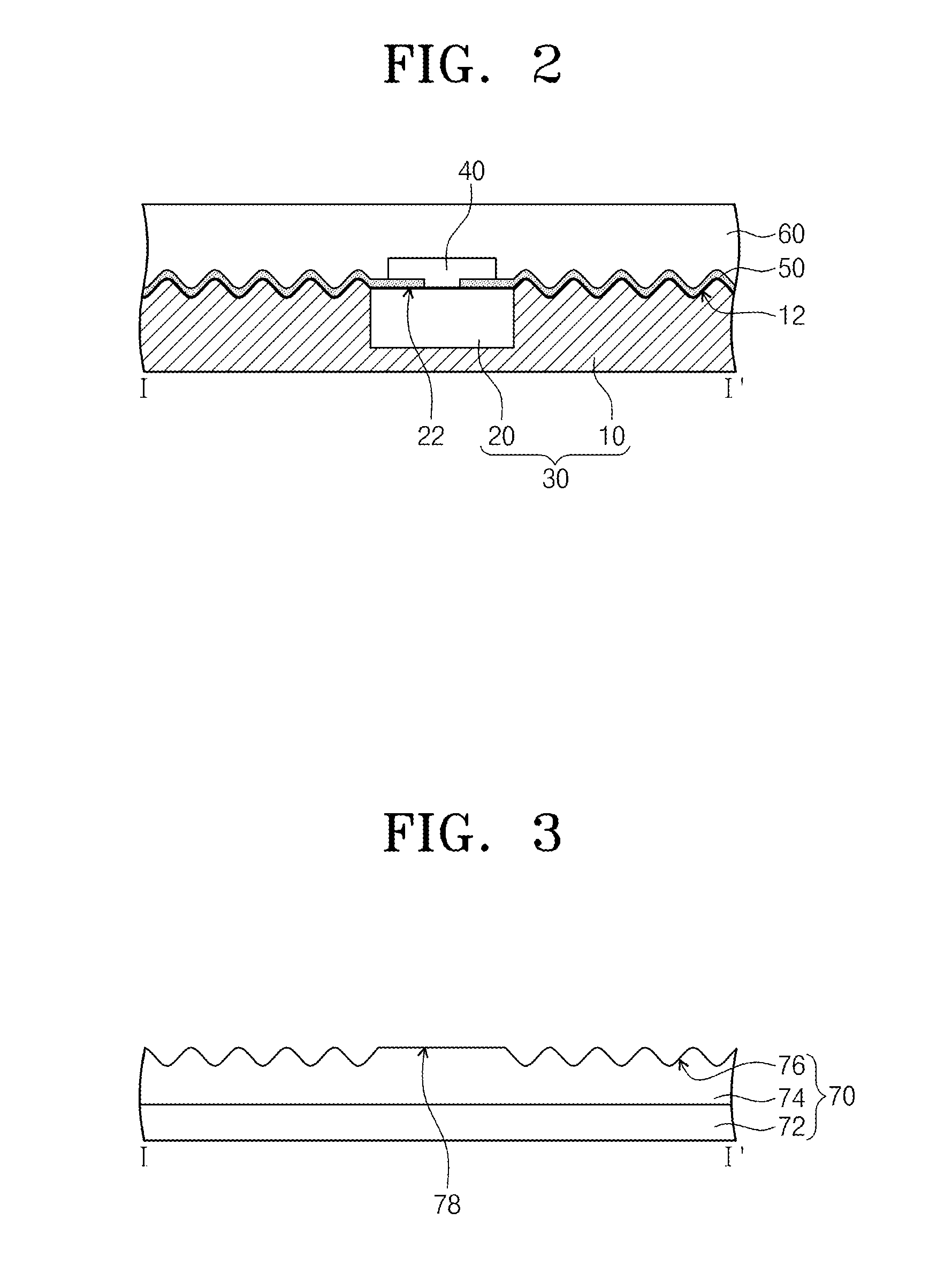
[0067]Referring again to FIG. 3, a mold substrate 70 is prepared. The mold substrate 70 may include a mold body 72 and a photoresist layer 74 formed on the mold body 72. The photoresist layer 74 may have a second corrugated surface 76 and a second flat surface 78. The second corrugated surface 76 and the second flat surface 78 may be formed at the same level on the photoresist layer 74.
[0068]Referring to FIG. 16, a low-stiffness body 10 is formed on the mold substrate 70. The low-stiffness body 10 may be formed by using a spin coating or dropping method. The low-stiffness body 10 may include addition-cure liquid silicone rubber (Sylgard 184). The low-stiffness body 10 may have a first corrugated surface 12 and a first corrugated surface 12.
[0069]Referring to FIG. 17, the mold substrate 70 is removed. The pho...
PUM
| Property | Measurement | Unit |
|---|---|---|
| Stiffness | aaaaa | aaaaa |
| Hardness | aaaaa | aaaaa |
| Stretchability | aaaaa | aaaaa |
Abstract
Description
Claims
Application Information