Light-emitting container

Inactive Publication Date: 2014-10-09
LA LUZ COMPANY
View PDF6 Cites 45 Cited by
  • Summary
  • Abstract
  • Description
  • Claims
  • Application Information

AI Technical Summary

Benefits of technology

[0105]There are several possible coil designs that would work in this device. There are differences in material thicknesses, diameters, coil lengths, and coil spacings that could make sense. In general, a copper coil with less than 25 revolutions is preferred, with spacing between the coils no more than five times that of the diameter of the coil. A single coil or two-coil design may be employed. The coil may also be designed to employ resonant coupling of the electromagnetic field. Resonant coupling increases the distance that energy may be transferred between the transmitting and receiving coils. In general, this distance would be less than 5 cm distance, and more likely to be 1-2 cm. With magnetic coupling this distance may be increased. However, resonant coupling also requires a more precise alignment of electromagnetic fields or the energy conversion efficiency can be negatively affected

Problems solved by technology

There are no existing commercial applications of a tilt-activated light-emitting bottle.
Many of these disadvantages are related to the inability to create adequate power management required to create a light-emitting device with the appropriate design to make the light appear brilliant and bright while being long-lasting with sufficient battery lift and compactness enough to fit inside a bottle package.
Batteries used are often too large or of too limited a voltage and capacity.
For example, alkaline batteries are 1.6V and most do not fit within a reasonable space.
Although circuit boards have been designed that include LEDs, there are no circuit boards currently used in combination with sens

Method used


Image

  • Light-emitting container
  • Light-emitting container
  • Light-emitting container

Examples


Example

[0129]The following detailed description and appended drawings describe and illustrate various exemplary embodiments of the invention. The description and drawings serve to enable one skilled in the art to make and use the invention, and are not intended to limit the present disclosure, application, or uses. In respect of the methods disclosed, the order of the steps presented is exemplary in nature, and thus, is not necessary or critical.

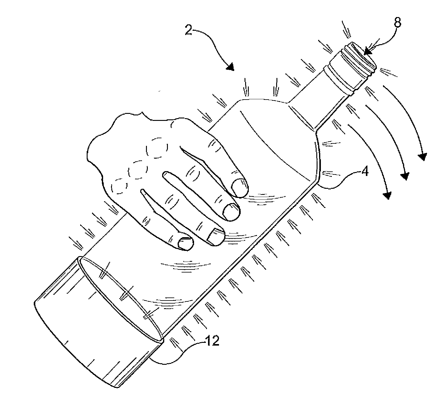
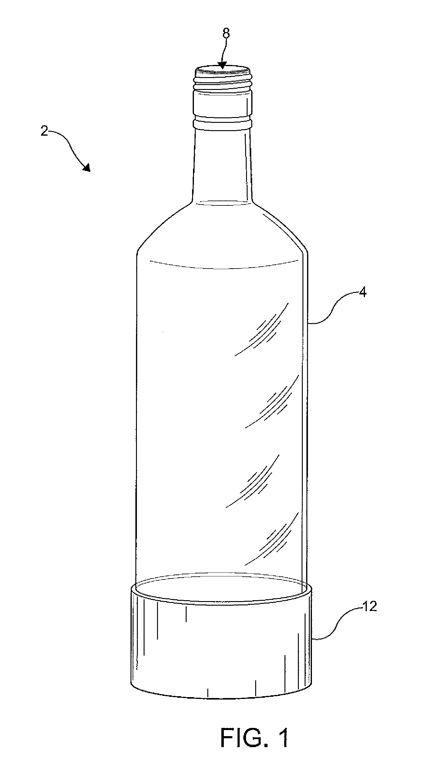
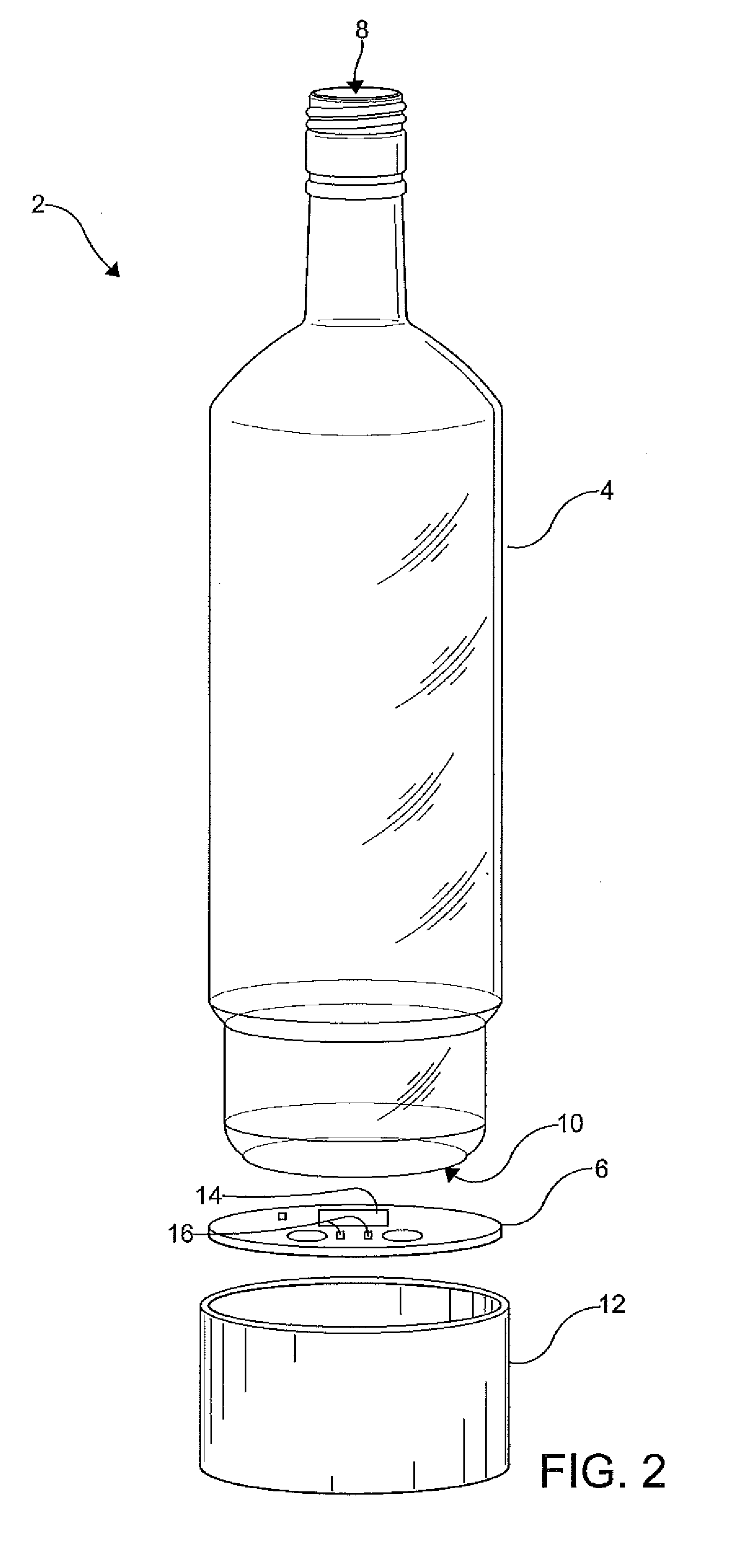
[0130]FIGS. 1-2 show a light-emitting container 2 according to one embodiment of the present disclosure. The light-emitting container 2 includes a hollow vessel 4 and a light-emitting device 6. The light-emitting container 2 has an open end 8 and a closed end 10. The light-emitting container 2 is one of transparent and translucent, and thereby permits light to be transmitted therethrough. As a nonlimiting example, the light-emitting container 2 may be a glass or plastic bottle configured to hold a liquid such as a beverage. Other types of container...


PUM


Abstract

A light-emitting container (2) such as a bottle includes a hollow vessel (4) and a light-emitting device (6). The vessel (4) has an open end (8) and a closed end (10). At least a portion of the vessel (4) is one of transparent and translucent. The light-emitting device (6) is disposed adjacent the closed end (10) of the vessel (4). The light-emitting device (6) includes a microcontroller (14) in electrical communication with at least one light source (16). The microcontroller (14) selectively causes one of an activation and a deactivation of the at least one light source (16). A light emitted from the at least one light source (16) is transmitted through the vessel (4) upon the activation of the at least one light source (16).

Description

CROSS-REFERENCE TO RELATED APPLICATIONS[0001]This application claims the benefit of U.S. Provisional Application No. 61 / 549,164, filed on Oct. 19, 2011, and U.S. Provisional Application No. 61 / 693,631, filed on Aug. 27, 2012. The entire disclosures of the above applications are hereby incorporated herein by reference.FIELD OF THE INVENTION[0002]The present disclosure relates to a light emitting container and, more particularly, to a tilt-activated light emitting bottle with a timer, in that the bottle can be lit periodically while sitting on a shelf to create an eye-catching display, or it can be tilted to emit an even more brilliant light while it is pouring the liquid.BACKGROUND OF THE INVENTION[0003]There are many types of beverages, both alcoholic and non-alcoholic that are available on the market. To differentiate the various brands and types of beverages that the consumer has an opportunity to sample or purchase, distinctive shapes, labels and colors are used on or in associat...

Claims


Application Information

Patent Timeline
IPC IPC(8): F21V33/00A47G19/22
CPCG09F23/06G09F2013/222G09F2023/0025A47G2019/2238F21V33/0036A47G19/2227A47G19/2205
Inventor LEBRUN, JEFFREY R.TONER, STEPHEN G.
Owner LA LUZ COMPANY
Why Eureka
Try Eureka