Magnetometer with Dual Purpose Reset and Calibration Coil

a magnetic field sensor and dual-purpose technology, applied in the field of magnetic field sensing devices, can solve the problems of insufficient development of methods for building high-performance mtj linear magnetic field sensors, insufficient sensitivity and/or dynamic range, cost, reliability and other factors, and achieve the effect of simplifying coil design

Active Publication Date: 2014-10-09
MULTIDIMENSION TECH CO LTD
View PDF2 Cites 9 Cited by
  • Summary
  • Abstract
  • Description
  • Claims
  • Application Information

AI Technical Summary

Benefits of technology

[0011]The present invention provides a method for mass production of linear magnetoresistive sensor bridges using a simplified coil design. The disclosed sensor uses MTJ or giant magnetoresistive (GMR) elements combined with a single on-chip coil for the calibration and set / reset operations. The magnetometer uses a low unipolar or bipolar current pulse cycle for the calibration operation, and a large unipolar current pulse for the reset operation.

Problems solved by technology

There are many different types of sensors in the prior art for measuring magnetic field, but these sensors have limitations that are well known in the art, such as, excessive size, inadequate sensitivity and / or dynamic range, cost, reliability and other factors.
Although MTJ devices are compatible with standard semiconductor fabrication processes, methods for building high performance MTJ linear magnetic field sensors have not been adequately developed.
In particular, performance issues due to temperature dependence and hysteresis are not easy to control.
Although bridge configurations do improve temperature compensation, the inherent temperature dependence of the magnetoresistance and magnetic properties of the sensor are not completely suppressed.
Because magnetoresistive sensors are composed of ferromagnetic sensing elements, the sensor response is subject to nonlinearities, offset, and hysteresis due to the formation and motion of domain walls within the sensor elements or other components, such as magnetic shields and flux concentrators.
The presence of both the calibration and set / reset coils adds complexity to magnetoresistive sensor fabrication by increasing the number of process steps required to manufacture the sensor, and it increases the size of the sensor die by requiring more contact pads and to accommodate the geometrical constraints required to produce the orthogonal calibration and set / reset fields.
A disadvantage of this approach is the fact that the sensitivity of the sensor cannot be measured by electrical means.
That is, if the magnetoresistive sensor does not have a calibration coil, the response of the sensor cannot be monitored and analyzed for sensitivity.
Moreover, implementing a standard self-test in the sensor is cumbersome.
This is however physically impossible.

Method used


Image

  • Magnetometer with Dual Purpose Reset and Calibration Coil
  • Magnetometer with Dual Purpose Reset and Calibration Coil
  • Magnetometer with Dual Purpose Reset and Calibration Coil

Examples


Embodiment Construction

[0035]The invention relates to an electronic device with a high accuracy magnetoresistive sensor to be used in low cost and possibly low power applications. Low-power sensors are particularly interesting for mobile electronic devices such as mobile telephones, watches, portable computers, or personal touch screen devices, etc. In particular, magnetoresistive sensors can be used to implement an electronic compass in order to provide a navigational reference with respect to the earth's magnetic field.

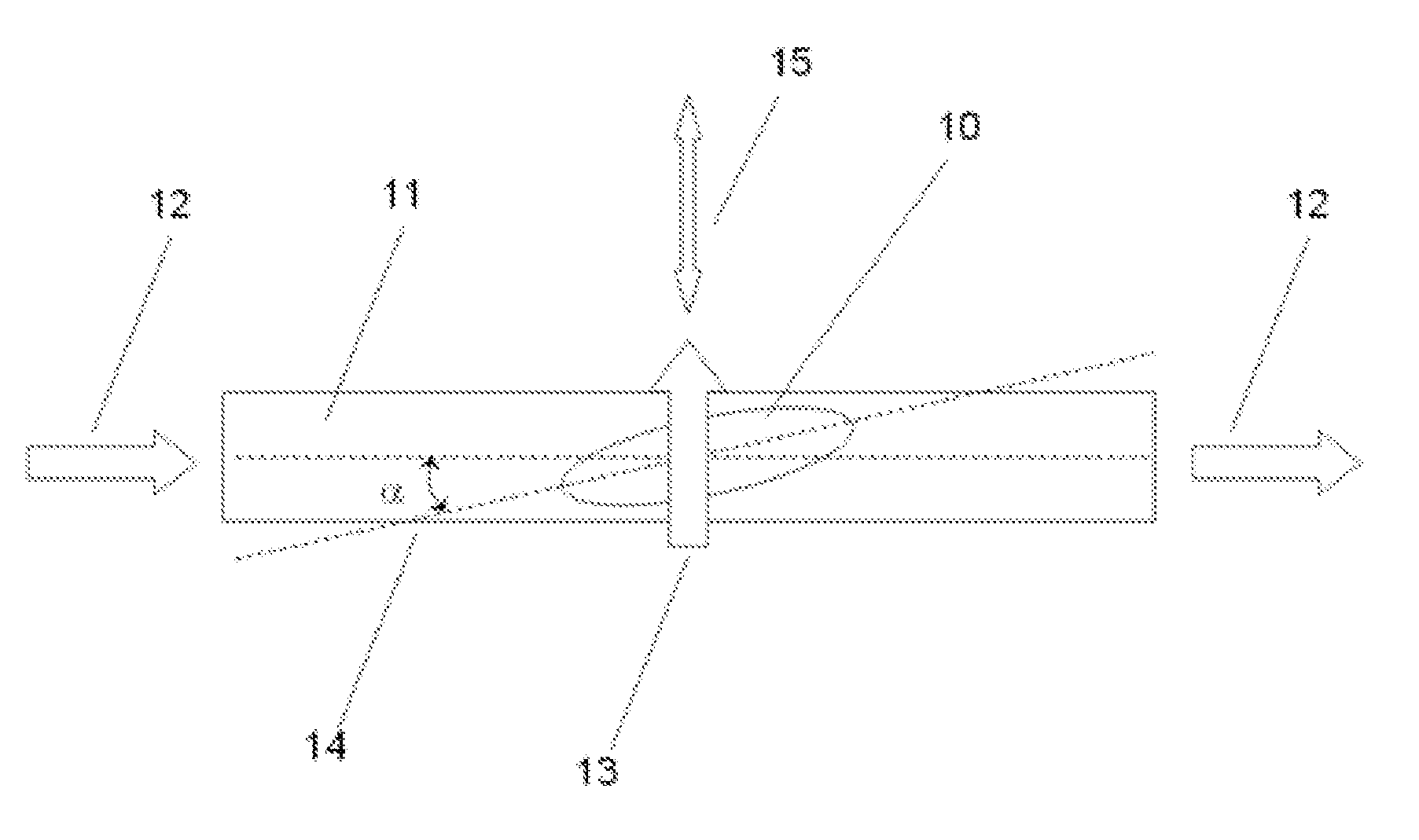
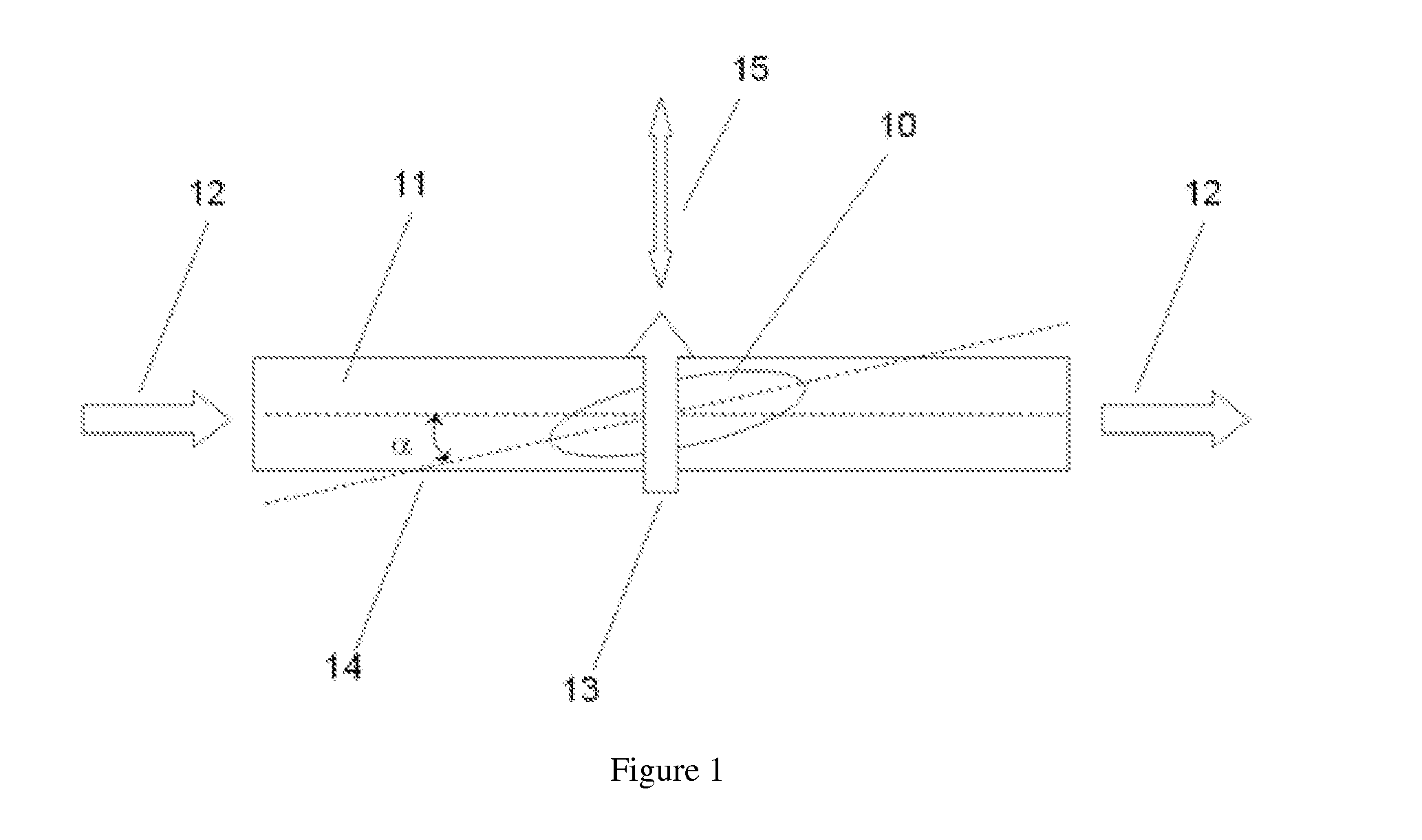
[0036]FIG. 1 illustrates the simplified concept of the sensing element and coil geometry. Here, a magnetoresistive sensor element 10 sits atop or beneath a conductor 11, through which a current 12 is sourced. The current 12 produces a magnetic field, B(I) 13 in a direction perpendicular to the current flow. The sensor 10 and conductor 11 may optionally be set at an angle 14 so that the magnetic field 13, is not perpendicular to the sensing direction 15 of the sensor 10.

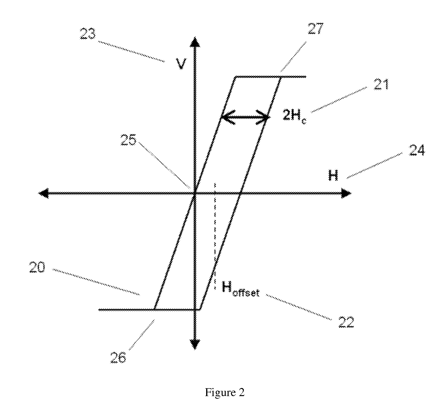
[0037]FIG. 2 depict...


PUM


Abstract

The present invention discloses a magnetic field sensing device that utilizes a single coil for calibrating the response of the sensor to compensate for temperature dependent sensitivity drift and also for resetting the magnetic field sensor in order to eliminate hysteresis. The single coil configuration is advantageous since it reduces the size of the sensor chip by decreasing the number of contact pads on the chip and also because it wastes less space, which permits an increase in the density of the magnetoresistive elements on the sensor chip.

Description

CROSS-REFERENCE TO A RELATED APPLICATION[0001]This application is a 35 U.S.C. §371 national phase application of PCT / CN2012 / 082015, filed on Sep. 26, 2012, which claims priority to a Chinese Patent Application No. CN 201110356226, filed on Aug. 30, 2011, incorporated herein by reference in its entirety.FIELD OF THE INVENTION[0002]This invention relates to a magnetic field sensing device.BACKGROUND OF THE INVENTION[0003]Magnetic sensors are widely used in modern systems to measure or detect physical parameters including but not limited to magnetic field strength, current, position, motion, orientation, and so forth. There are many different types of sensors in the prior art for measuring magnetic field, but these sensors have limitations that are well known in the art, such as, excessive size, inadequate sensitivity and / or dynamic range, cost, reliability and other factors.[0004]Hence, there is a need for improved magnetic sensors, especially sensors that can be easily integrated wit...

Claims


Application Information

Patent Timeline
Patent Type & Authority Applications(United States)
IPC IPC(8): G01R35/00G01R33/00
CPCG01R33/0017G01R35/005G01R33/0035G01R33/007
Inventor DEAK, JAMES GEZASHEN, WEIFENGLEI, XIAOFENGXUE, SONGSHENG
Owner MULTIDIMENSION TECH CO LTD
Why Eureka
Try Eureka