Method for recognizing a manipulation of a sensor and/or sensor data of the sensor

Active Publication Date: 2014-10-09
ROBERT BOSCH GMBH
View PDF2 Cites 30 Cited by
  • Summary
  • Abstract
  • Description
  • Claims
  • Application Information

AI Technical Summary

Benefits of technology

[0006]The present invention is intended to provide a method for recognizing a manipulation of transmitted sensor data and/or a sensor itself, which meets similarly high security demands as the complex method

Problems solved by technology

However, such tuning is not recognizable and not comprehensible for the vehicle manufacturer.
This has the disadvantage that the vehicle manufacturer in the past was made liable for any problems which resulted from the impermissible performance enhancement and had to repair defects of the internal combustion engine, although these were sometimes to be attributed to the impermissible performance enhancement.
Many o

Method used


Image

  • Method for recognizing a manipulation of a sensor and/or sensor data of the sensor
  • Method for recognizing a manipulation of a sensor and/or sensor data of the sensor
  • Method for recognizing a manipulation of a sensor and/or sensor data of the sensor

Examples


Embodiment Construction

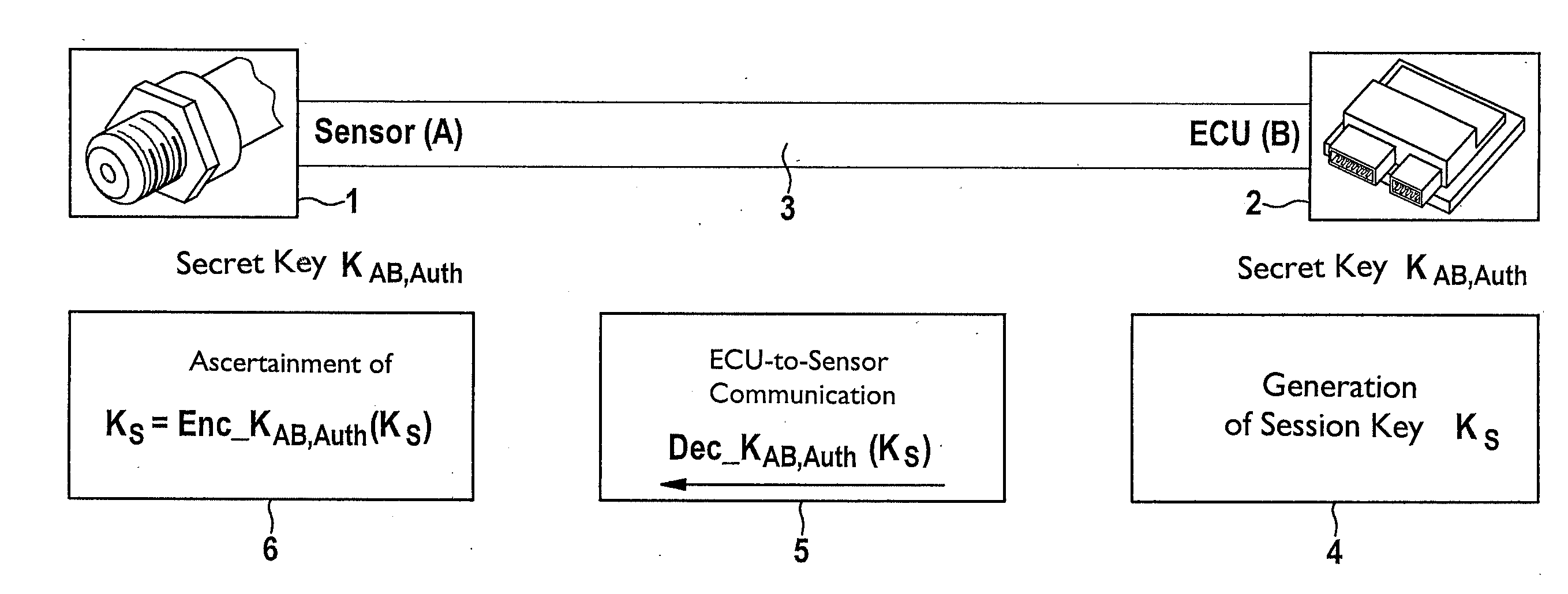
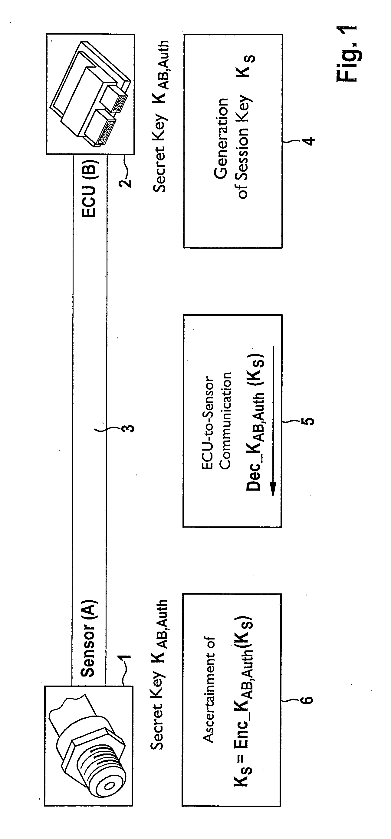
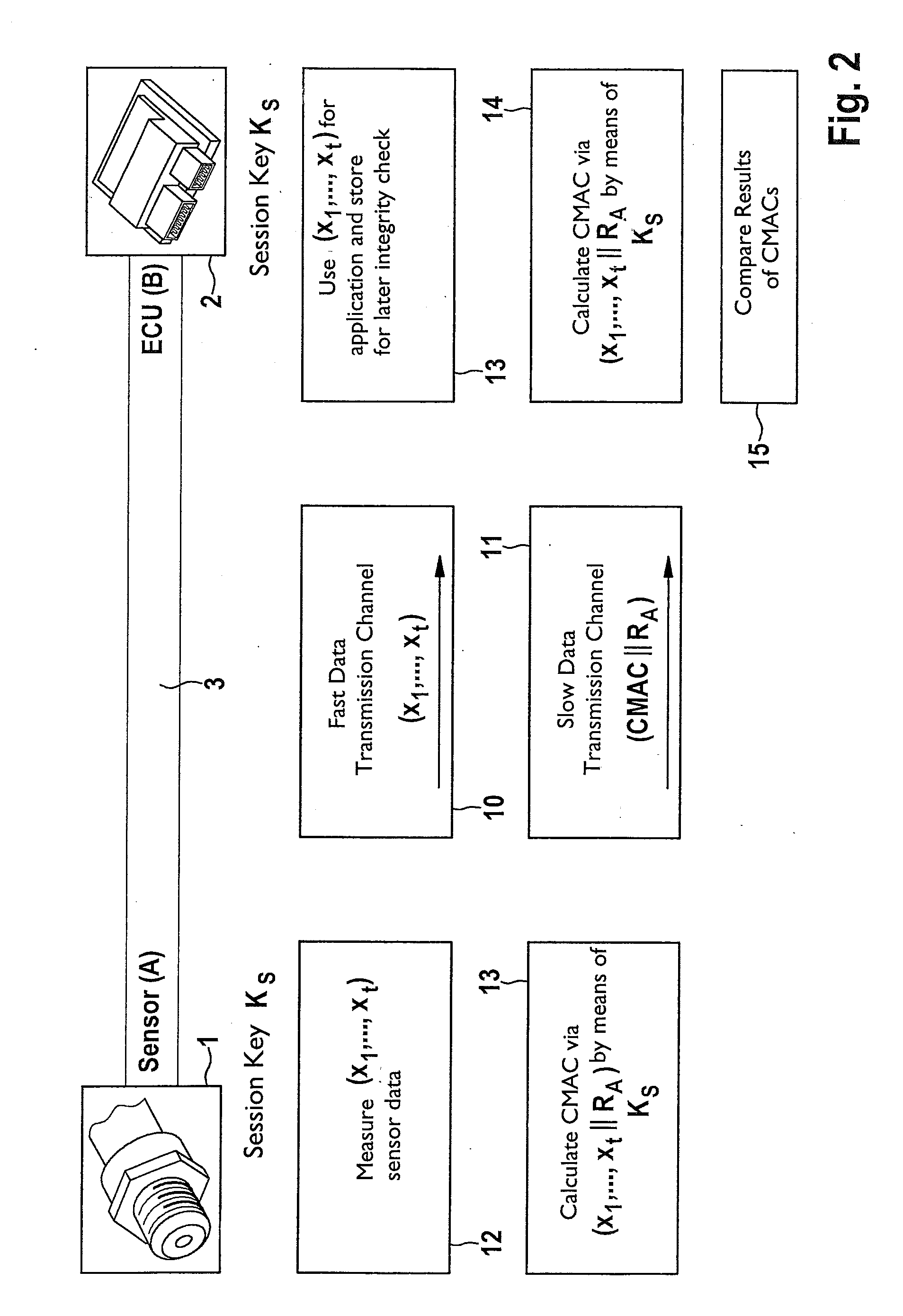
[0034]The present invention relates to a method for data transmission between a sensor and an electronic control and / or regulating unit (ECU). A manipulation of the transmitted sensor data and / or the sensor may be recognized. A sensor A is shown in the figures, which is identified with reference numeral 1. A control and / or regulating unit (ECU) B is identified with reference numeral 2. Sensor 1 may be connected via a physical data transmission channel in the form of a data transmission connection 3 to ECU 2. Data transmission connection 3 includes, for example, a two-wire line. Multiple data transmission channels are implemented on data transmission connection 3, via which data are transmitted between sensor 1 and ECU 2. Sensor 1 is configured, for example, as a pressure sensor for detecting the fuel pressure in a shared fuel accumulator (for example, common rail) of a fuel injection system of an internal combustion engine of a motor vehicle. Such a sensor 1 detects the fuel pressur...


PUM


Abstract

A method for data transmission between a sensor and an electronic control and/or regulating unit (ECU), the transmitted sensor data (x1, . . . , xt) and the sensor being secured against a manipulation. The system provides a particularly simple, but very secure method for manipulation protection, the sensor data (x1, . . . , xt) being transmitted via a first logical data transmission channel at a first data transmission rate, and security data (MAC; CMAC) for securing the transmitted sensor data and/or the sensor being transmitted via a second logical data transmission channel at a second data transmission rate from the sensor to the ECU. At least once at the beginning of a data transmission session, a session key is transmitted from the ECU to the sensor via a third logical data transmission channel and received by the latter, the session key being used at least for the ongoing session to generate the security data.

Description

RELATED APPLICATION INFORMATION[0001]The present application claims priority to and the benefit of German patent application no. 10 2013 206 185.4, which was filed in Germany on Apr. 9, 2013, the disclosure of which is incorporated herein by reference.FIELD OF THE INVENTION[0002]The present invention relates to a method for data transmission between a sensor and an electronic control and / or regulating unit, a manipulation of the transmitted sensor data and / or the sensor being recognized. The present invention additionally relates to a sensor, which is provided for connection to an electronic control and / or regulating unit and is configured to transmit sensor data to the control and / or regulating unit, an arrangement being provided for recognizing a manipulation of the transmitted sensor data and / or the sensor. Furthermore, the present invention relates to a control and / or regulating unit, which is provided for connection to a sensor and is configured to receive sensor data from the ...

Claims


Application Information

Patent Timeline
IPC IPC(8): H04L9/08
CPCH04L2209/24H04L9/0825H04L9/0637H04L9/0822H04L9/3226H04L2209/84
Inventor LEWIS, MATTHEWIHLE, MARKUSSZERWINSKI, ROBERTSHOKROLLAHI, JAMSHIDGLAS, BENJAMIN
Owner ROBERT BOSCH GMBH
Why Eureka
Try Eureka