Broken rotor bar detection based on current signature analysis of an electric machine

a technology of current signature analysis and electric machines, applied in the direction of electric motor control, control systems, instruments, etc., can solve the problems of rotor bars, drive-train failure, and variety of faults in the electrical mechanical system

Inactive Publication Date: 2014-10-09
GE ENERGY POWER CONVERSION TECH
View PDF4 Cites 24 Cited by
  • Summary
  • Abstract
  • Description
  • Claims
  • Application Information

AI Technical Summary

Problems solved by technology

Electromechanical systems may experience variety of faults such as drive-train failure, bearing faults, broken rotor bars, and the like.
It has been observed that mechanical faults in rotor bars produce vibrations in radial rotor movement which in turn produce torque oscillations at the rotor mechanical rotating frequency.
The monitoring and study of the rotor mechanical rotating frequency may lead to detecting mechanical faults associated with the rotor bars.
However, condition monitoring using vibration signals has numerous disadvantages such as background noise due to external excitation motion, sensitivity to the installation position, the invasive nature of the measurement equipment, and proximity of frequencies of faulty operation with the operating frequency of the electromechanical machine.
Unlike vibration monitoring, for which industry standards have been developed from long-time field experience, the field experience in stator current monitoring is limited, and significant difficulties exist.
The aforementioned techniques are not always capable of distinguishing fault signatures from the normal operation signatures, when rotor bars of the electric machine are faulty.

Method used


Image

  • Broken rotor bar detection based on current signature analysis of an electric machine
  • Broken rotor bar detection based on current signature analysis of an electric machine
  • Broken rotor bar detection based on current signature analysis of an electric machine

Examples


Embodiment Construction

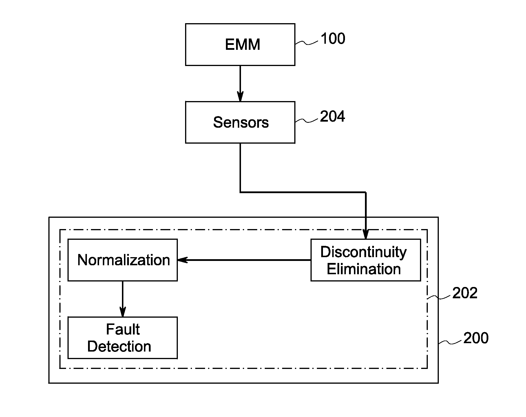
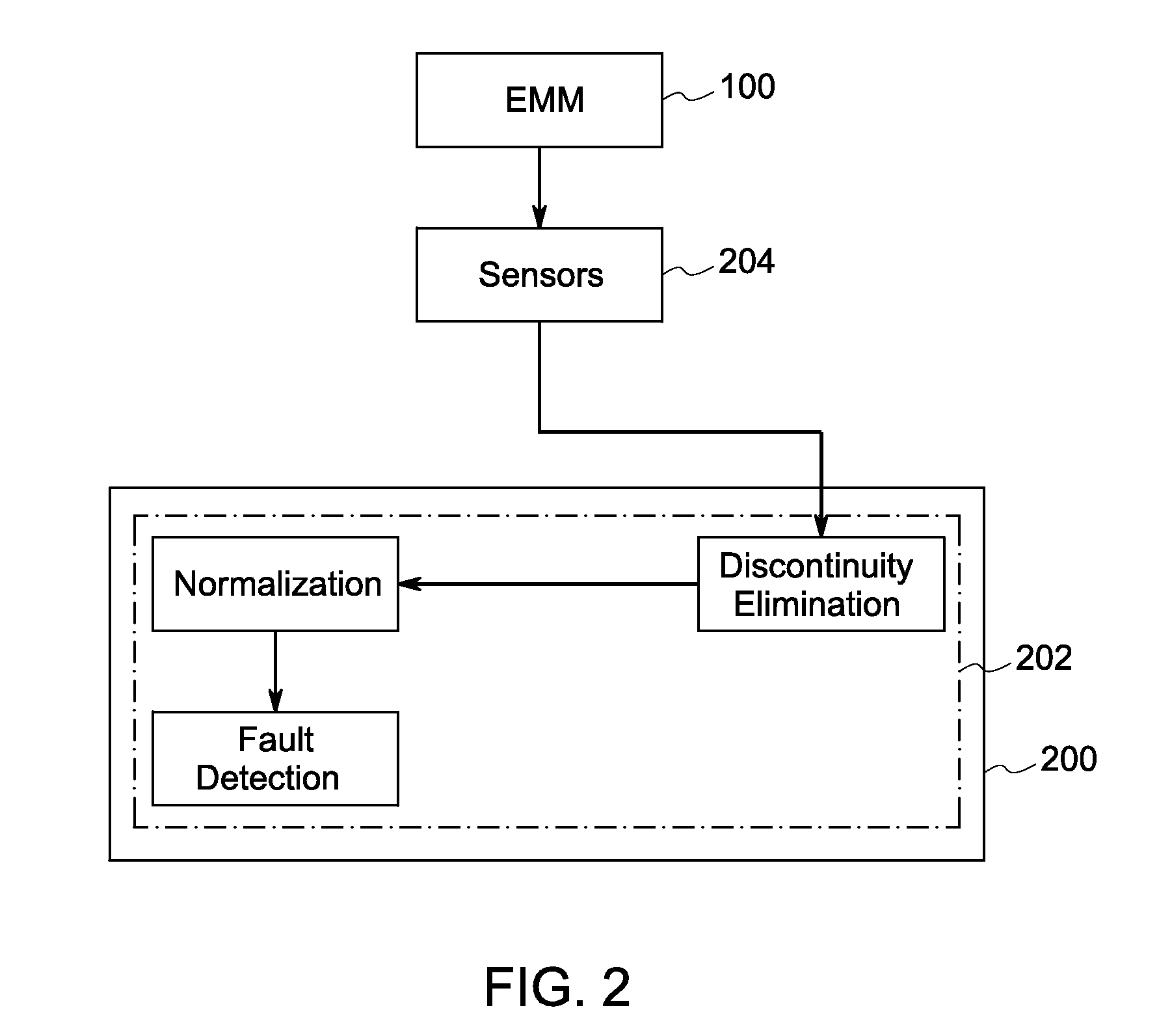
[0013]Reference will be made below in detail to exemplary embodiments of the invention, examples of which are illustrated in the accompanying drawings. Wherever possible, the same reference numerals used throughout the drawings refer to the same or like parts.

[0014]A spectrum analysis based technique for high sensitivity detection of broken rotor bar faults in an electromechanical machine (EMM) is described herein. The technique provides for differentiating a faulty EMM rotor bar's condition from normal or admissible conditions based on possibly subtle changes in the magnitude of electric signatures received from the EMM. The dominant components in electric signals received from a typical electromechanical machine are the supply fundamental and harmonics, the eccentricity harmonics, the slot harmonics, the saturation harmonics, and other components from unknown sources including environmental noise. Since such dominant components exist before and after the presence of rotor bar faul...


PUM


Abstract

A method for detection of rotor bar faults in an electric machine is provided. The method includes acquiring electrical signals from the electric machine that are representative of the operative condition of the machine. The symmetrical components from the electrical signals are eliminated by squaring an instantaneous value of each data point from the electrical signals and summing the squared values. The method further includes the step of eliminating discontinuities in the electrical signals by applying a window function to compute weighted representation of the squared values. Furthermore, the method includes the step of normalizing the weighted representation to obtain spectral information. The faults in the rotor bar are detected by analyzing the spectral information obtained after normalization.

Description

BACKGROUND[0001]The present invention relates, generally, to the field of monitoring electric machines, and, more particularly, to broken rotor bar detection in electric machines based on current signature analysis.[0002]Electromechanical systems are widely used in variety of application areas such as power generation systems, manufacturing units, factories, electronic appliances, oil rigs, and the like. Electromechanical systems may experience variety of faults such as drive-train failure, bearing faults, broken rotor bars, and the like. It is of paramount importance to detect a fault in electric machines to ensure that losses caused by such faults are minimized to a great extent. Different techniques for fault detection that are employed at present include, but are not limited to, vibration and acoustic noise analysis, electromagnetic field monitoring and axial flow measurement, temperature measurement, infrared recognition, and spectral analysis of current in the machine.[0003]Co...

Claims


Application Information

Patent Timeline
Patent Type & Authority Applications(United States)
IPC IPC(8): G01R31/34
CPCG01R31/34G01R31/343H02P29/0241
Inventor NETI, PRABHAKARZHANG, PINJIAGRUBIC, STEFAN
Owner GE ENERGY POWER CONVERSION TECH
Why Eureka
Try Eureka