Rigid raft for a gas turbine engine

Active Publication Date: 2014-10-16
ROLLS ROYCE PLC
View PDF144 Cites 6 Cited by
  • Summary
  • Abstract
  • Description
  • Claims
  • Application Information

AI Technical Summary

Benefits of technology

The patent describes a rigid raft that can be used to transfer electrical signals and fluids in an engine. The raft provides better protection and reduces assembly and maintenance times compared to conventional harnesses. It also reduces the possibility of errors and increases the service life of components that were previously mounted without anti-vibration mounts. The technical effects of the patent include improved protection, reduced assembly time, and increased service life of components.

Problems solved by technology

This makes the conventional harness itself bulky, heavy and difficult to manipulate.
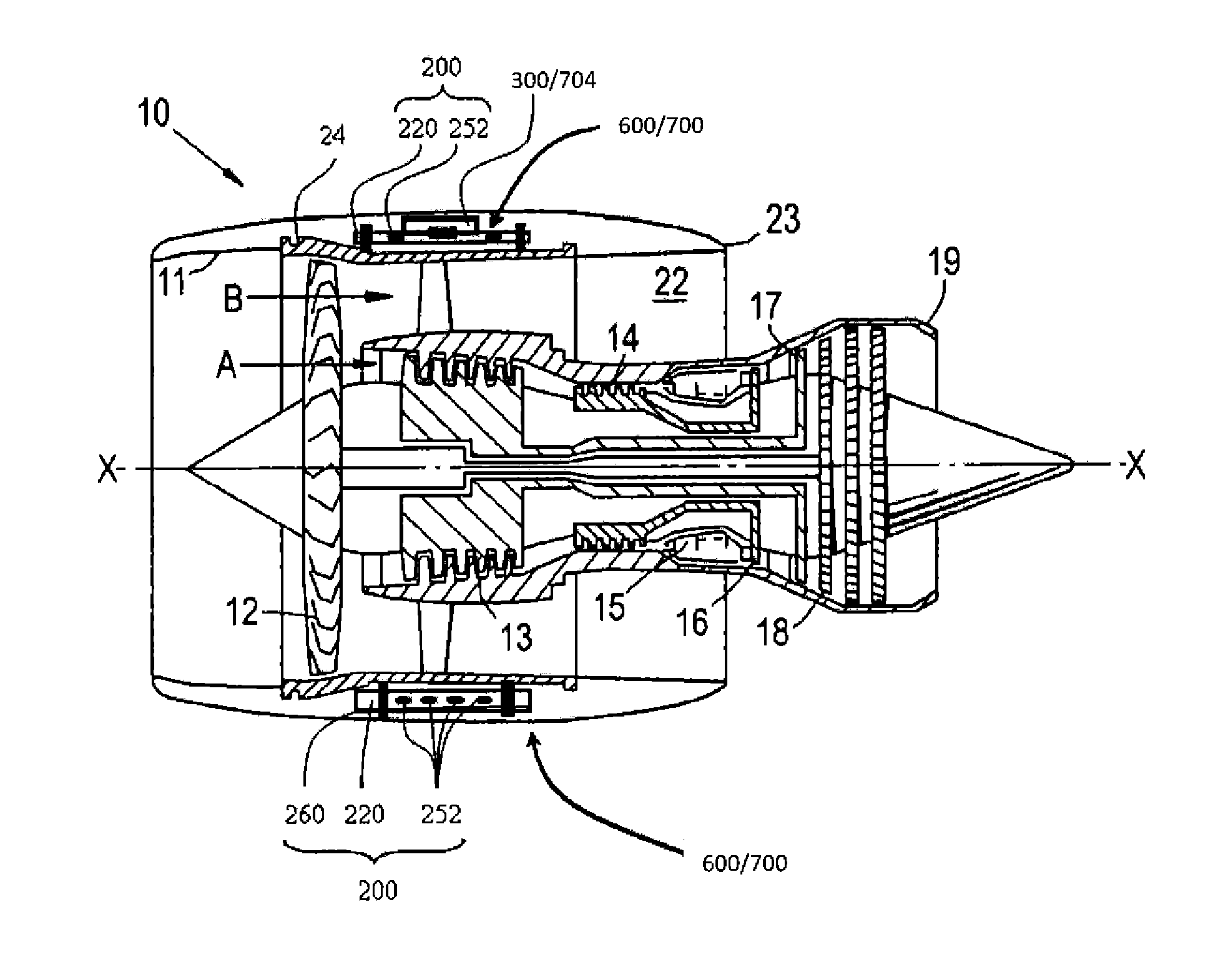
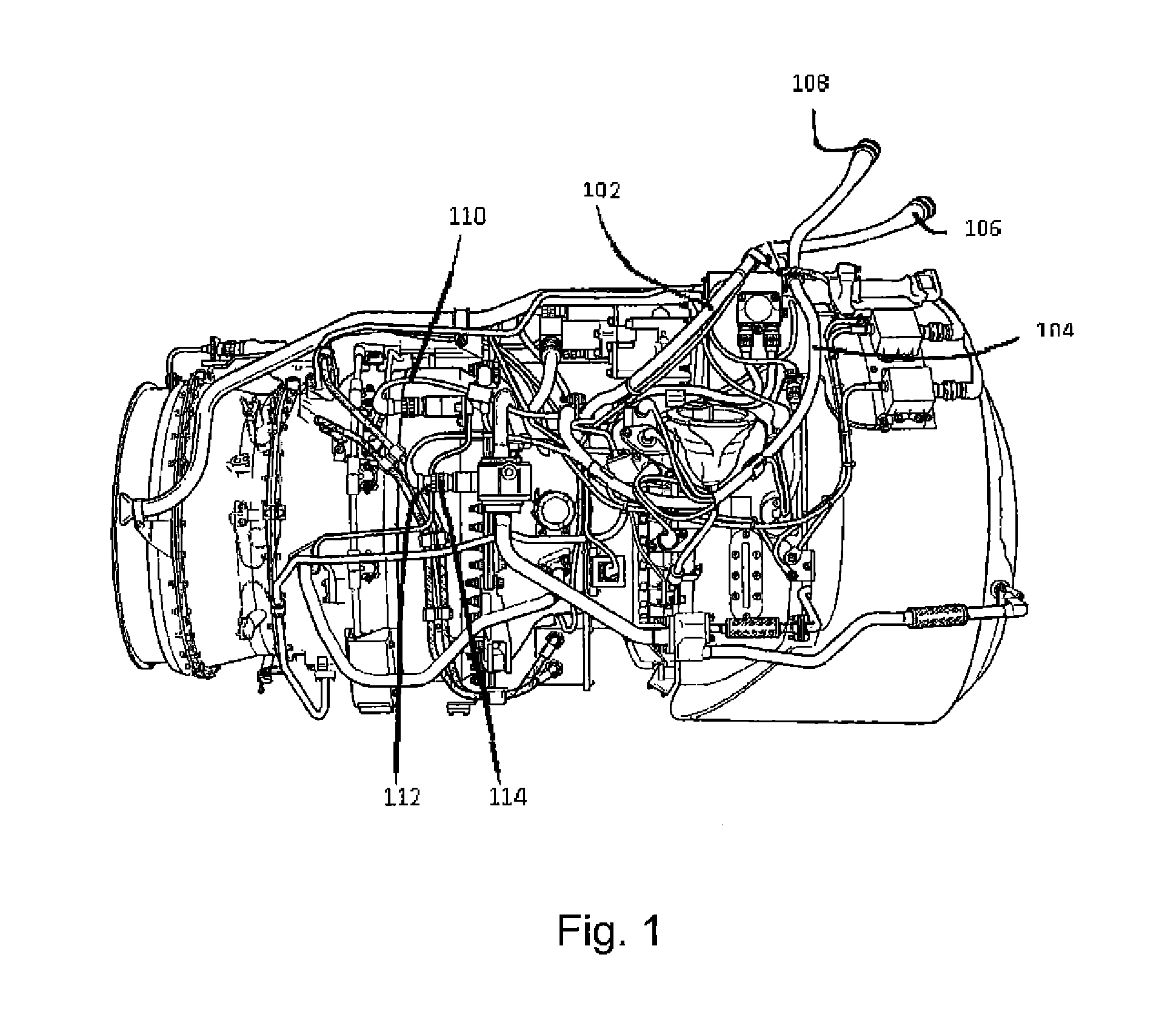
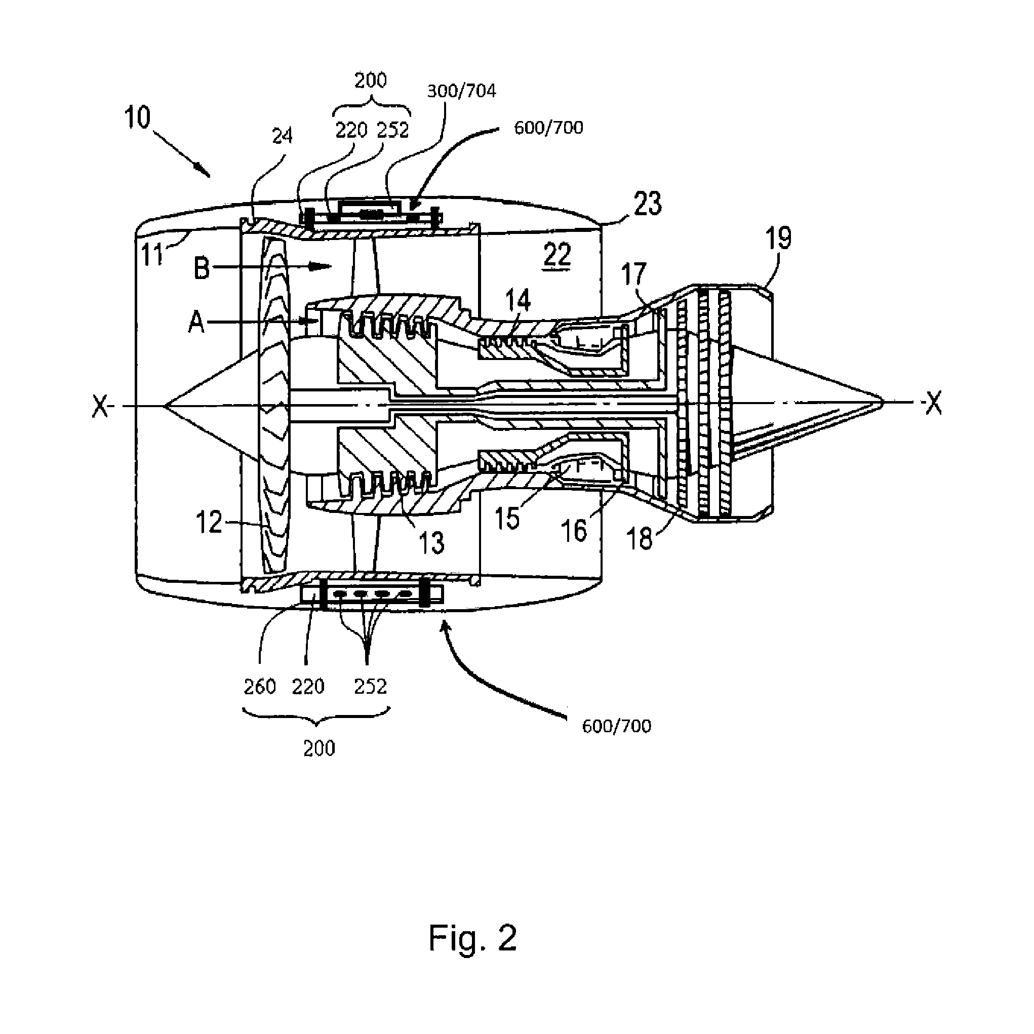
The conventional harnesses occupy significant space within a gas turbine engine (for example within the nacelle of a gas turbine engine), and thus may compromise the design of the aircraft, for example the size and / or weight and / or shape of the nacelle.
This can make the assembly process complicated (and thus susceptible to errors) and / or time consuming.
Disassembly of the conventional harnesses (for example removal of the conventional harnesses from a gas turbine engine during maintenance) may also be complicated and / or time consuming.
Thus, in many maintenance (or repair or overhaul) procedures on a gas turbine engine, removal and subsequent refitting of the conventional electrical harness may account for a very significant portion of the operation time and / or account for a significant proportion of the potential assembly errors.
The electrical conductors in the conventional harnesses may be susceptible to mechanical damage.
For example, mechanical damage may occur during installation (for example through accidental piercing of the protective sleeves / braiding) and / or during service (for example due to vibration).
In order to reduce the likelihood of damage to the conductors in a conventional harness, the protective sleeves / braiding may need to be further reinforced, adding still further weight and reducing the ease with which they can be manipulated.
Similarly, the exposed electrical connectors used to connect one conductor to another conductor or conductors to electrical units may be susceptible to damage and / or may add significant weight to the engine.
This requires still further dedicated brackets and / or fixings to be provided, thereby still further adding to the weight and / or complexity of the engine.
Further, the use of such rafts may significantly reduce the build and maintenance times of an engine, and / or reduce the possibility of errors occurring during such procedures.
If such components come loose, they might lead to further damage to themselves or other engine components.
However, non-metallic tethers may be used.
For example, some maintenance procedures may only require access to a certain portion of the gas turbine engine that only requires a part of the harness to be removed.
It may be difficult and / or time consuming, or not even possible, to only remove the required part of a conventional harness from a gas turbine engine.
However, it may be relatively straightforward to only remove the relevant electrical raft, for example by simply disconnecting it from the engine and any other electrical rafts / components to which it is connected.
Such a rigid composite material may be particularly stiff and / or lightweight.
The environment of a gas turbine engine during operation may be particularly severe, with, for example, high levels of vibration and / or differential expansion between components as the temperature changes through operation and as the components move relative to each other.

Method used


Image

  • Rigid raft for a gas turbine engine
  • Rigid raft for a gas turbine engine
  • Rigid raft for a gas turbine engine

Examples


Embodiment Construction

[0067]With reference to FIG. 2, a ducted fan gas turbine engine generally indicated at 10 has a principal and rotational axis X-X. The engine 10 comprises, in axial flow series, an air intake 11, a propulsive fan 12, an intermediate pressure compressor 13, a high-pressure compressor 14, combustion equipment 15, a high-pressure turbine 16, an intermediate pressure turbine 17, a low-pressure turbine 18 and a core engine exhaust nozzle 19. The engine also has a bypass duct 22 and a bypass exhaust nozzle 23.

[0068]The gas turbine engine 10 works in a conventional manner so that air entering the intake 11 is accelerated by the fan 12 to produce two air flows: a first air flow A into the intermediate pressure compressor 13 and a second air flow B which passes through the bypass duct 22 to provide propulsive thrust. The intermediate pressure compressor 13 compresses the air flow A directed into it before delivering that air to the high pressure compressor 14 where further compression takes ...


PUM


Abstract

A rigid raft is provided for a gas turbine engine. The raft has an electrical system and / or a fluid system embedded in the material of the raft. The raft further has one or more first mounts for mounting the raft to the gas turbine engine, and one or more second mounts for mounting a gas turbine engine component to the raft. The raft further has one or more tethers which extend between respective first and second mounts and are embedded in the material of the raft.

Description

CROSS-REFERENCE TO RELATED APPLICATIONS[0001]This application is based upon and claims the benefit of priority from British Patent Application Number 1306674.1 filed 12 Apr. 2013, the entire contents of which are incorporated by reference.BACKGROUND OF THE INVENTION[0002]1. Field of the Disclosure[0003]The present disclosure relates to a rigid raft for a gas turbine engine, and particularly to a rigid raft to which a gas turbine engine component can be mounted.[0004]2. Description of the Related Art[0005]A typical gas turbine engine has a substantial number of electrical components which serve, for example, to sense operating parameters of the engine and / or to control actuators which operate devices in the engine. Such devices may, for example, control fuel flow, variable vanes and air bleed valves. The actuators may themselves be electrically powered, although some may be pneumatically or hydraulically powered, but controlled by electrical signals.[0006]Electrical power, and signal...

Claims


Application Information

Patent Timeline
IPC IPC(8): F02C9/00F02C7/00
CPCB60R16/02F02C9/00F02C7/00F02C7/32F05D2300/43F05D2300/603F01D25/28Y02T50/60B64D27/00H02G3/04H02G3/00
Inventor AMARASINGHE, ASHANWILLMOT, MICHAEL CHRISTOPHER
Owner ROLLS ROYCE PLC
Why Eureka
Try Eureka