Critical flow in moisture generation system for natural gas

a technology of moisture generation system and critical flow, which is applied in the field of liquefaction of natural gas, can solve the problems of uneconomical transportation of natural gas in the gaseous state, overcapacity, and overdemand of the lin

Active Publication Date: 2014-10-16
BAKER HUGHES INC
View PDF2 Cites 2 Cited by
  • Summary
  • Abstract
  • Description
  • Claims
  • Application Information

AI Technical Summary

Problems solved by technology

Often the capacity will exceed demand while at other times the demand may exceed the capacity of the line.
Transportation of natural gas in the gaseous state would be uneconomical unless the natural gas was highly compressed, and then the system would not be economical because it would be impractical to provide containers of suitable strength and capacity.
Another example is that moisture condensation can corrode equipment.
As yet another example is that elevated moisture can cause ice formation that can severely damage cryogenic equipment if the amount of ice is significant.
In other words, it is sometimes useful to check / test the operation of the moisture analyzer.
Such accumulation of moisture could adversely affect components of the moisture provision and analyzer arrangement.
Also, such accumulation of moisture could adversely affect the operation / accuracy of the moisture analyzer within the arrangement.
It has also been noted that discontinuity of flow rate can cause some disruption of the ability of the moisture analyzer to properly function and provide an accurate indication of perceived moisture.
As one specific example, an overshoot of moisture provision may occur.

Method used


Image

  • Critical flow in moisture generation system for natural gas
  • Critical flow in moisture generation system for natural gas
  • Critical flow in moisture generation system for natural gas

Examples


Embodiment Construction

[0021]Example embodiments that incorporate one or more aspects of the invention are described and illustrated in the drawings. These illustrated examples are not intended to be a limitation on the invention. For example, one or more aspects of the invention can be utilized in other embodiments and even other types of devices. Moreover, certain terminology is used herein for convenience only and is not to be taken as a limitation on the invention. Still further, in the drawings, the same reference numerals are employed for designating the same elements.

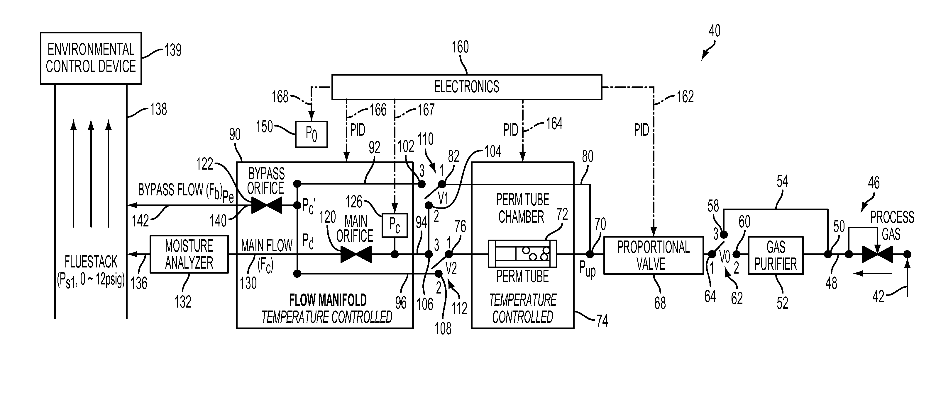
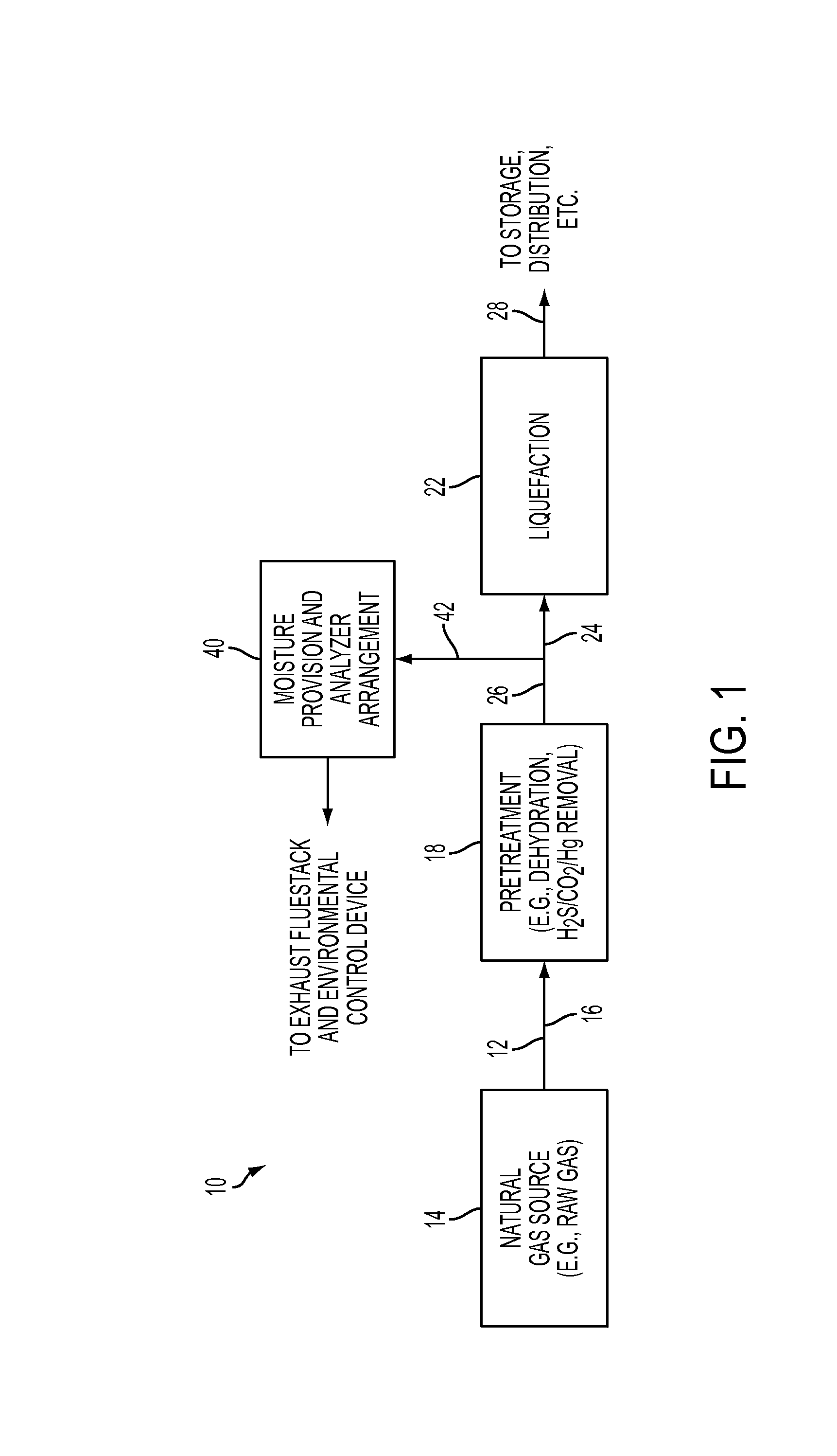
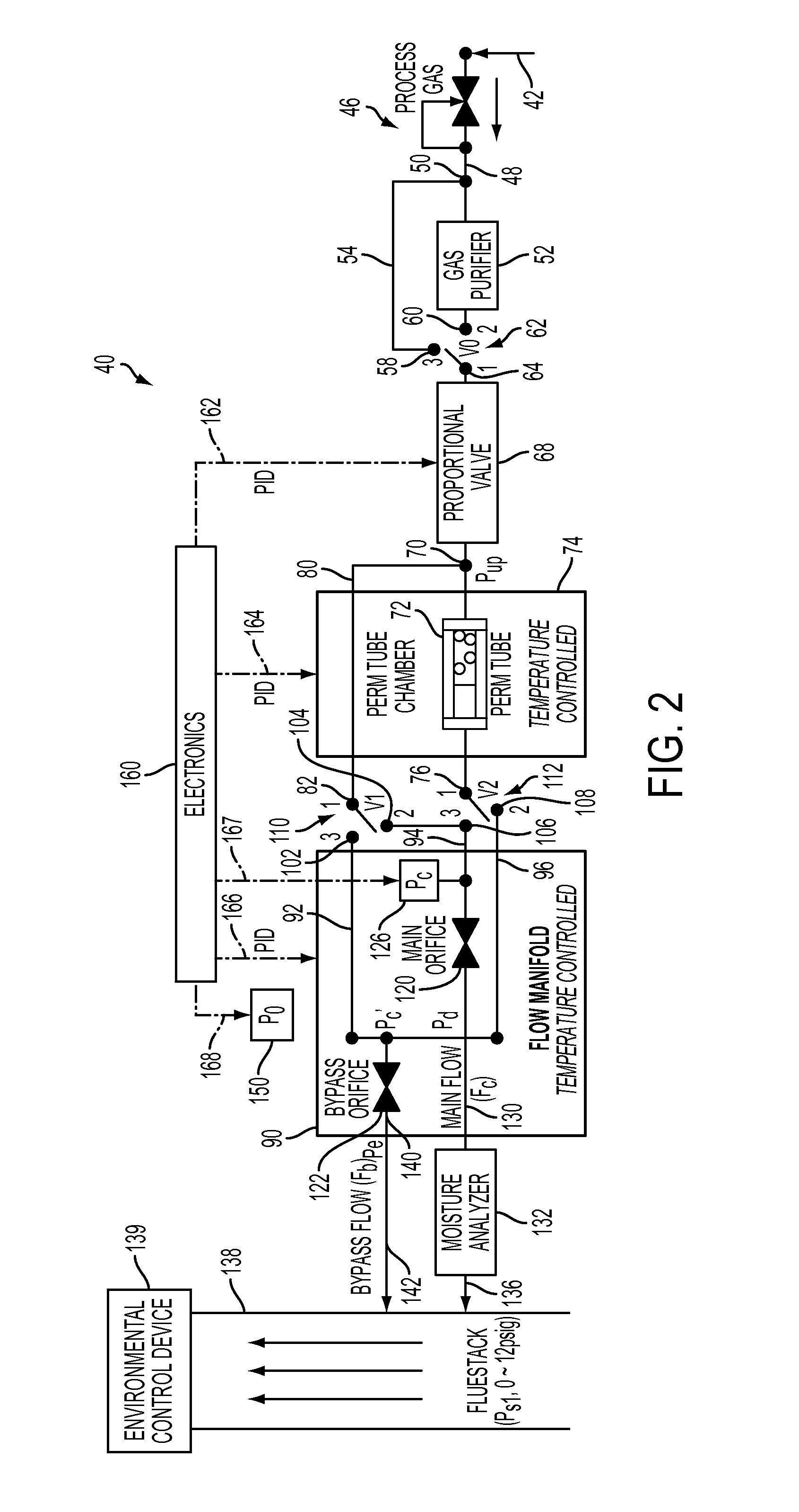
[0022]An example embodiment of a liquefied natural gas (LNG) processing system 10 that includes at least one aspect in accordance with the present invention is schematically shown within in FIG. 1. It is to be appreciated that the system 10 shown within FIG. 1 is simply one example and that other examples that include at least one aspect in accordance with the present invention are possible and contemplated.

[0023]Turning to the example...


PUM

PropertyMeasurementUnit
temperatureaaaaaaaaaa
pressureaaaaaaaaaa
pressureaaaaaaaaaa

Abstract

A moisture provision and analyzer arrangement includes a conduit for obtaining a sample flow of natural gas, a moisture analyzer, and a bypass flow conduit. A main orifice is in fluid communication within the moisture provision and analyzer arrangement with flow proceeding to the moisture analyzer. A bypass orifice is located along the bypass flow conduit. The main orifice is sized and the flow provided to the moisture analyzer via the main orifice is at a pressure such that the flow provided to the moisture analyzer is at a critical flow condition and the bypass orifice is sized and the bypass flow is provided at a pressure such that the bypass flow is at a critical flow condition. Components in the moisture provision and analyzer arrangement are selected such that the critical flow rate through the main orifice and the critical flow rate through the bypass orifice are equal.

Description

BACKGROUND OF THE INVENTION[0001]1. Field of the Invention[0002]The present invention relates to the liquefaction of natural gas, and more particularly, the present invention relates to monitoring moisture within natural gas prior to the natural gas proceeding to liquefaction.[0003]2. Discussion of Prior Art[0004]Various reasons exist for liquefaction (i.e., the process of making liquid) of gases and particularly of natural gas. One example reason for the liquefaction of raw natural gas is the separation / liquefied into different hydrocarbon components. Another example reason for the liquefaction of natural gas is that the liquefaction reduces the volume of a gas by a factor of about 1 / 600, thereby making it possible to store and transport the liquefied gas in containers of more economical and practical design. In one example, when gas is transported by pipeline from a source / supply to a distant market, it is desirable to operate under a substantially constant high load factor. Often...

Claims


Application Information

Patent Timeline
Patent Type & Authority Applications(United States)
IPC IPC(8): G01N33/00
CPCG01N33/0004G01N33/225G01N33/007G01N2033/0072
Inventor HUANG, YUFENGPARECE, GARY STEPHENPOOLE, JOHN MCKINLEY
Owner BAKER HUGHES INC
Why Eureka
Try Eureka