MEMS Inertial Sensor and Method of Inertial Sensing

a technology of inertial sensing and sensing device, which is applied in the direction of acceleration measurement using interia force, devices using electric/magnetic means, instruments, etc., can solve the problems of increasing manufacturing cost, and achieve the effects of increasing sensitivity, high quality, and increasing parametric sensitivity

Active Publication Date: 2014-10-16
SILICON MICROGRAVITY LTD
View PDF1 Cites 15 Cited by
  • Summary
  • Abstract
  • Description
  • Claims
  • Application Information

AI Technical Summary

Benefits of technology

[0009]The present invention proposes an alternative approach to mode-localized inertial sensing by deducing an acceleration / rotation rate input through a direct transduction of an inertial displacement, rather than an induced differential strain. This approach, whilst offering the advantages of improvements in signal sensitivity and enhanced environmental robustness (relative to the more traditional frequency-shift based sensors) as in the case of the strain modulated mode-localized sensors, also offers two additional key benefits:
[0058]The invention uses the phenomena of mode localization and vibration energy confinement to provide a measure of inertial force. The change in relative displacement between the proof mass and the first resonant element alters the stiffness of the first resonant element. Unlike the conventional approach of measuring induced frequency shifts, mode-localized sensors in accordance with the invention rely on tracking shifts in relative amplitudes of vibration between two or more vibrating elements. This enhances the parametric sensitivity and in effect, the resolution of such MEMS inertial sensors. The use of electrostatic coupling between the proof mass and a first resonant element also increases sensitivity and allows for the use of high quality factor resonators, such as bulk acoustic wave type resonators, that are less affected by air damping.

Problems solved by technology

This consequently imposes stringent limitations on the packaging of these sensors and consequently, increases the cost of manufacture.

Method used


Image

  • MEMS Inertial Sensor and Method of Inertial Sensing
  • MEMS Inertial Sensor and Method of Inertial Sensing
  • MEMS Inertial Sensor and Method of Inertial Sensing

Examples


Embodiment Construction

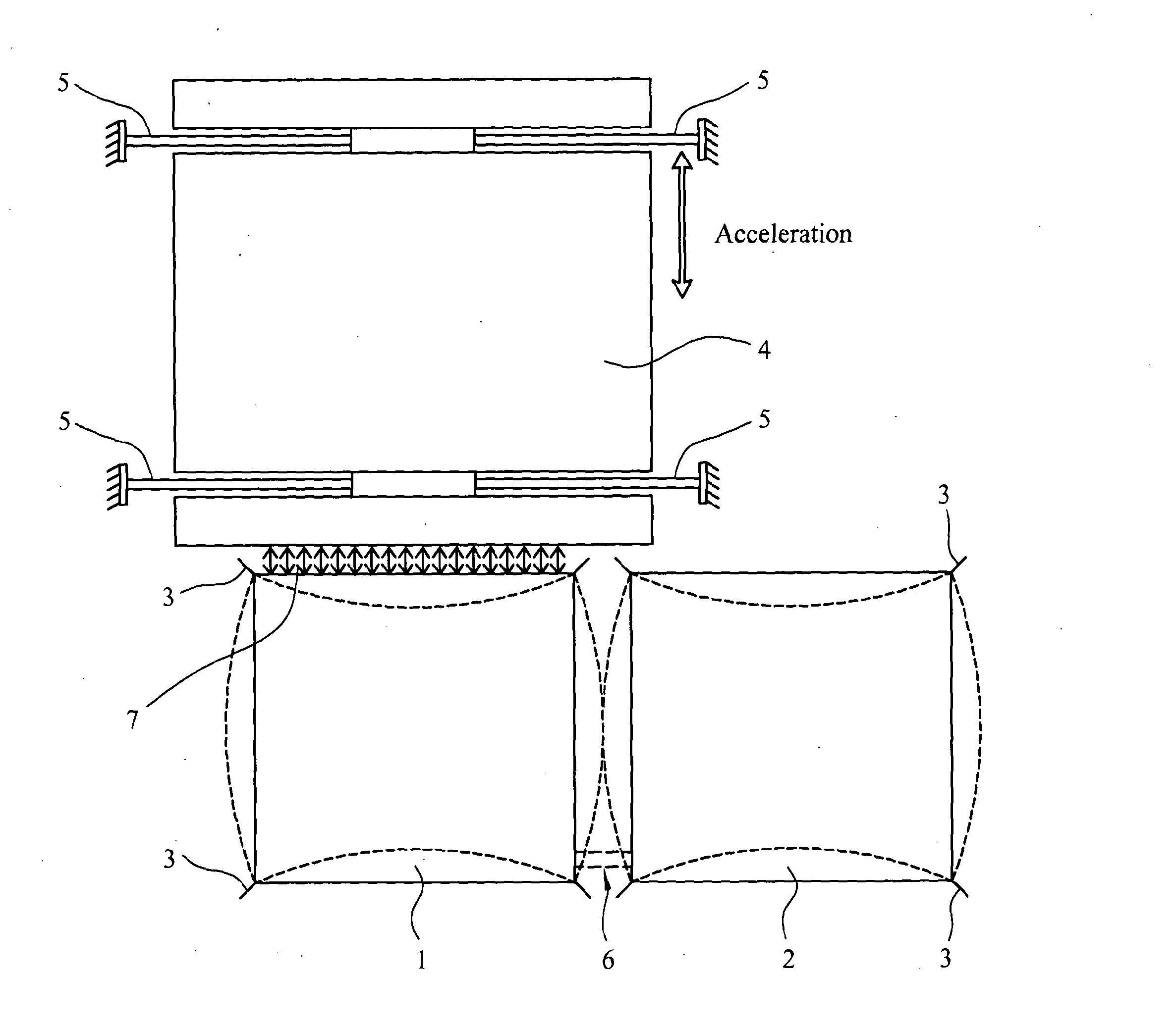
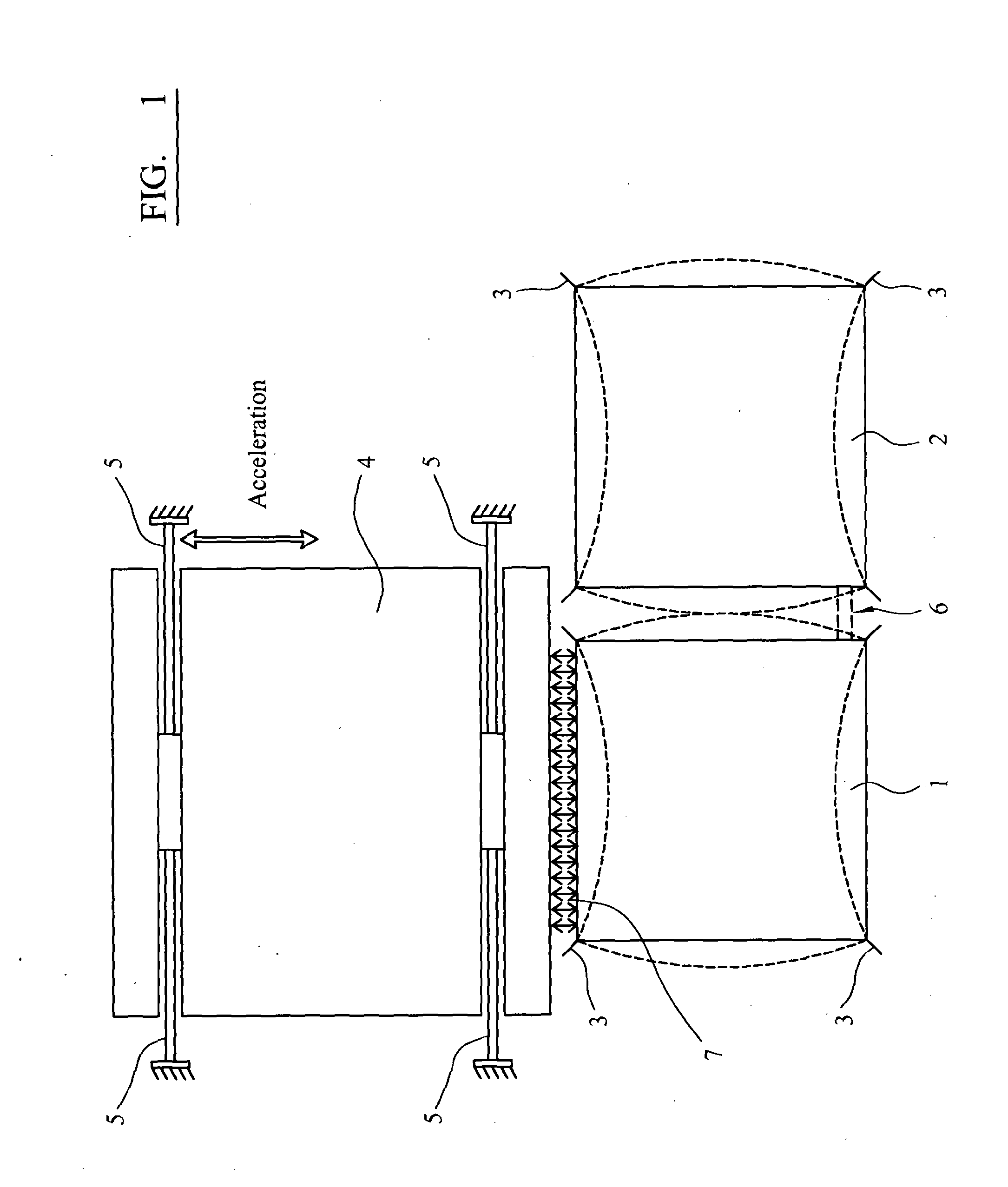
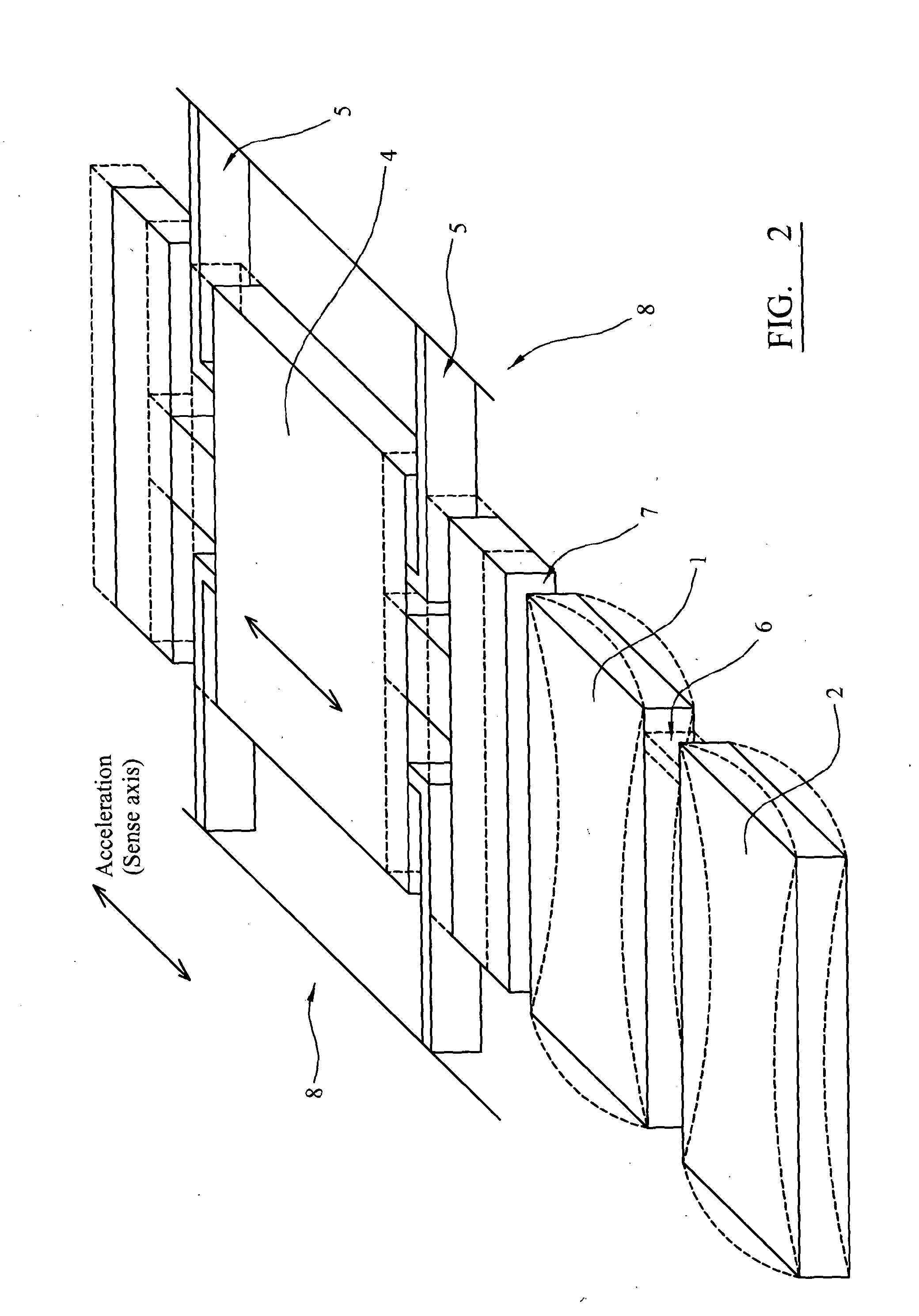
[0069]FIG. 1 illustrates a sensor in accordance with a first embodiment of the invention. The sensor comprises two resonant elements 1, 2, which in this example are bulk acoustic wave (BAW) resonators. The two resonant elements 1, 2 are adjacent to one another and fixed to a substrate or frame by flexures 3. The first resonant element 1 is capacitively coupled to a proof mass 4, which is suspended from the frame by flexures 5. The two resonant elements are weakly coupled by a mechanical coupling element 6.

[0070]Mode localization in a device of this type may be illustrated by considering the simple case of two weakly coupled resonant elements with masses m1 and m2 and stiffnesses k1 and k2. One of the resonant elements is coupled to a proof mass by a capacitive air gap. When the two resonant elements are perfectly identical (m1=m2=m; k1=k2=k) the system is symmetric about the coupling, which has a stiffness kc. When the device experiences an acceleration, the proof mass displaces by ...


PUM


Abstract

The invention comprises an inertial sensor comprising a frame, a proof mass, a first resonant element, the first resonant element being fixed to the frame and electrostatically coupled to the proof mass, and a second resonant element, the second resonant element being fixed to the frame, adjacent to the first resonant element such that there is substantially no electrostatic coupling between the second resonant element and the proof mass. A coupling is provided between the first resonant element and the second resonant element. A drive means is coupled to the first and second resonant elements for vibrating the first and second resonant elements and a sensor assembly is provided for detecting the amplitude of vibration of at least one of the resonant elements.

Description

FIELD OF THE INVENTION[0001]The present invention relates to inertial sensors and methods of inertial sensing using microscopic mechanical inertial sensors.BACKGROUND TO THE INVENTION[0002]Accelerometers and gyroscopes are in wide use today for a variety of motion sensing applications ranging from inertial navigation to vibration monitoring. Accelerometers measure changes in acceleration (linear or rotational) while gyroscopes provide information about angular motion (rotation). These devices use the inertial properties of light or matter for their operation and have hence been broadly classified as ‘inertial sensors’.[0003]Inertial sensors have traditionally served navigation markets. Macroscale gyroscopes and accelerometers are used to provide information about the position, orientation and velocity for aircraft and naval vessels. They have also been incorporated into control systems that are used for robotic applications, such as missile guidance, unmanned aircraft, and industria...

Claims


Application Information

Patent Timeline
Patent Type & Authority Applications(United States)
IPC IPC(8): G01C19/5712
CPCG01C19/5719G01C19/5712G01P15/097
Inventor THIRUVENKATANATHAN, PRADYUMNASESHIA, ASHWIN
Owner SILICON MICROGRAVITY LTD
Why Eureka
Try Eureka