Engine bearing block assembly

a technology of bearing blocks and components, applied in the direction of sliding contact bearings, rigid support of bearing units, machines/engines, etc., can solve the problems of large heat generation loss, large heat loss of oil used to lubricate bearing assemblies, and large loss of heat generated by conduction into the cylinder block. , to achieve the effect of increasing fuel usage, increasing wear, and significant friction loss

Inactive Publication Date: 2014-10-16
FORD GLOBAL TECH LLC
View PDF35 Cites 9 Cited by
  • Summary
  • Abstract
  • Description
  • Claims
  • Application Information

AI Technical Summary

Benefits of technology

[0007]Following a start-up from cold, that is an engine start-up where the temperature of the engine is originally close to ambient temperature, significant friction losses are produced due to the lubricating oil being below an optimum operating temperature. These losses increase fuel usage during the initial warm-up period and, in addition, increase wear if the oil is below a minimum temperature at which additives in the oil become fully activated. In an effort to reduce these losses it has been proposed to insulate an oil feed passage of the engine so as to reduce the loss of heat from the oil, thereby speeding up the oil heating process and reducing fuel usage. While such an approach produces a significant reduction in oil warm-up time, the heat lost from oil within a rotating shaft bearing of such an engine is not reduced.
[0008]As such in one approach, a bearing block assembly in an engine is provided. The bearing block assembly comprises at least one bearing block to rotatably support an oil lubricated shaft and fastening apparatus to attach the at least one bearing block to a flat mounting surface on a large engine component and a thermal barrier positioned between the shaft and the flat mounting surface and configured to reduce the loss of heat to the large engine component from oil used to lubricate the shaft. In this way, heat loss from oil used to lubricate a rotatable shaft bearing assembly of an engine is reduced. Additionally, the aforementioned engine bearing assembly is simple in construction, thereby reducing the cost and complexity of manufacture of the engine component to which it is fastened.

Problems solved by technology

Such a manufacturing arrangement is complex, time consuming and requires the engine component to include intricate shapes and forms to provide the half bearings.
A further problem with such an arrangement is that, due to the thermally conductive nature of such a bearing assembly, the majority of the heat transferred to oil used to lubricate the bearing assembly is lost by conduction into the very large mass constituted by the engine component.
For example, in the case of a main bearing assembly, a large portion of the heat generated is lost by way of conduction to the cylinder block.
Following a start-up from cold, that is an engine start-up where the temperature of the engine is originally close to ambient temperature, significant friction losses are produced due to the lubricating oil being below an optimum operating temperature.
These losses increase fuel usage during the initial warm-up period and, in addition, increase wear if the oil is below a minimum temperature at which additives in the oil become fully activated.
While such an approach produces a significant reduction in oil warm-up time, the heat lost from oil within a rotating shaft bearing of such an engine is not reduced.

Method used


Image

  • Engine bearing block assembly
  • Engine bearing block assembly
  • Engine bearing block assembly

Examples


Embodiment Construction

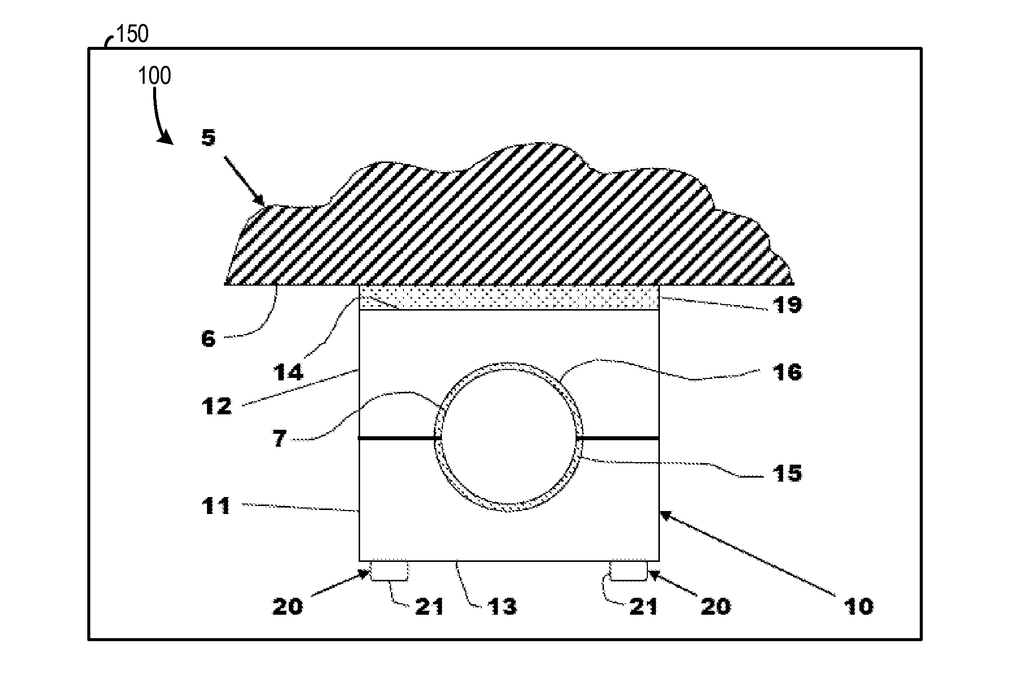
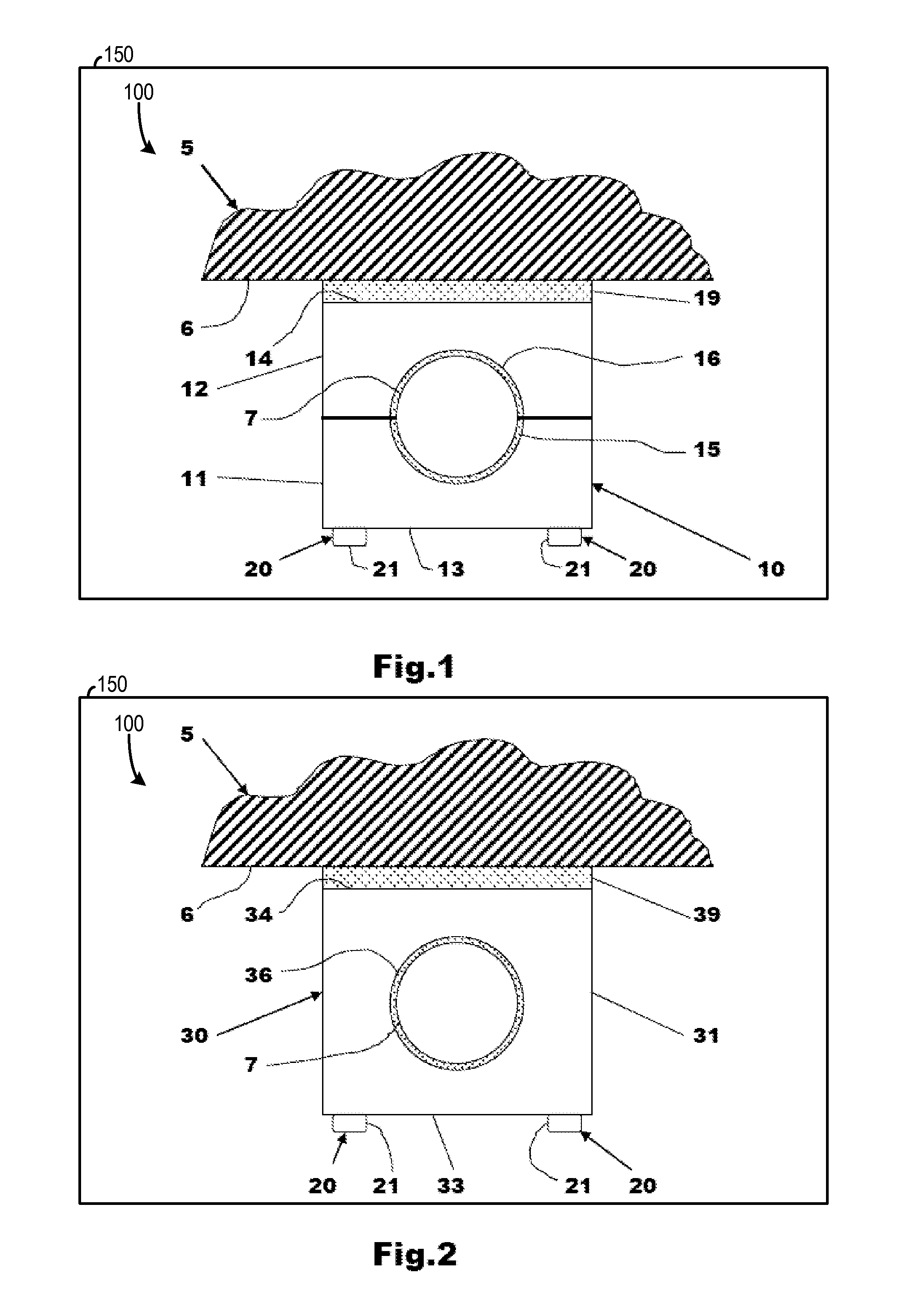
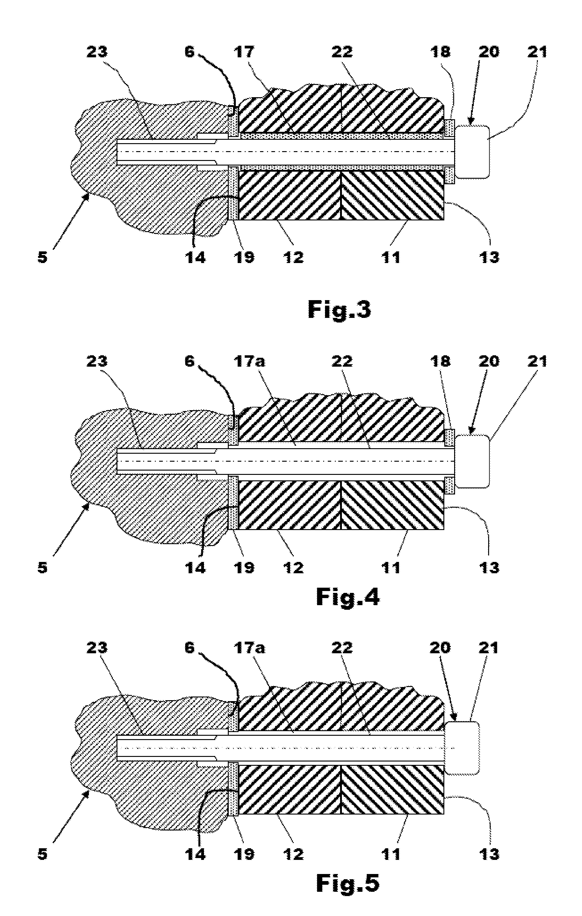
[0021]A bearing block assembly in an engine is described herein. The bearing block assembly may include at least one bearing block to rotatably support an oil lubricated shaft and fastening apparatus to attach the at least one bearing block to a flat mounting surface on a large engine component and a thermal barrier positioned between the shaft and the flat mounting surface and configured to reduce the loss of heat to the large engine component from oil used to lubricate the shaft. In this way, heat loss from oil used to lubricate a rotatable shaft bearing assembly of an engine is reduced. Additionally, the aforementioned engine bearing assembly is simple in construction, thereby reducing the cost and complexity of manufacture of the engine component to which it is fastened.

[0022]The bearing block assembly may include first and second bearing blocks and the fastening apparatus may comprise a pair of spaced apart threaded fasteners that extend through holes in the two bearing blocks ...


PUM


Abstract

A bearing block assembly in an engine is provided. The bearing block assembly includes at least one bearing block to rotatably support an oil lubricated shaft and fastening apparatus to attach the at least one bearing block to a flat mounting surface on a large engine component and a thermal barrier positioned between the shaft and the flat mounting surface configured to reduce the loss of heat to the large engine component from oil used to lubricate the shaft.

Description

CROSS REFERENCE TO RELATED APPLICATIONS[0001]The present application claims priority to G.B. Patent Application No. 1306506.5, “AN ENGINE BEARING BLOCK ASSEMBLY,” filed Apr. 10, 2013, the entire contents of which are hereby incorporated by reference for all purposes.FIELD[0002]The present disclosure relates to bearing assemblies used to rotatably support a shaft of an engine and in particular to an improved engine bearing block assembly.BACKGROUND AND SUMMARY[0003]It is known in the art to provide a bearing assembly for rotating a shaft of an engine, such as for example a crankshaft main bearing assembly, a camshaft bearing assembly, and a balancer shaft bearing assembly.[0004]Such prior art bearing assemblies may use a bearing structure in which a half bearing part of the bearing assembly is formed as an integral part of the engine component used to support the bearing assembly such as, for example, a cylinder block of the engine in the case of a crankshaft main bearing assembly or...

Claims


Application Information

Patent Timeline
Patent Type & Authority Applications(United States)
IPC IPC(8): F16C17/12
CPCF16C17/12F16C2360/22F16C35/02F16C17/243F16C33/105F16C2202/24F16C2206/56F02F7/0053F01M2005/008F01L2001/0476F01M5/005F02F7/007F16C9/02
Inventor PEGG, IAN GRAHAMHELLE-LORENTZEN, ROBERTFAWCETT, NIGEL PHILIP HAROLDSTARK, ROLAND PAUL
Owner FORD GLOBAL TECH LLC
Why Eureka
Try Eureka