Method and Device for Suppressing Electrical Fires in Underground Conduit

a technology of underground conduits and electrical fires, applied in fire rescue, medical science, dental surgery, etc., can solve the problems of fires which must be quickly extinguished, conduits carrying these utilities wear out and break, and electrical transmission lines in conduits and tunnels fail

Active Publication Date: 2014-10-16
REGER MICHAEL L
View PDF16 Cites 2 Cited by
  • Summary
  • Abstract
  • Description
  • Claims
  • Application Information

AI Technical Summary

Benefits of technology

[0023]It is a further objective of the present invention to provide a method of installing that allows a receptacle to be inserted into a conduit, with or without electrical wires, and filled with a predetermined amount of fire suppressant or compositions thereof providing a non conductive material for use in fire suppression and extinguishment.
[0024]It is a further objective of the present invention to provide a receptacle that can be placed within a flexible material housing for ease of positioning within aging conduit or conduit containing obstacles such as existing wires.

Problems solved by technology

Over time, the conduits which carry these utilities wear out and break.
A serious problem is the failure of electrical transmission lines in conduits and tunnels.
These failures usually result in fires which must be quickly extinguished to prevent further damage.
While it is desirable to replace very old utilities in conduits and tunnels, it is not always practical.
Due to financial restraints and other limitations, most of these electrical transmission lines have not been replaced, yet higher electrical demands are placed on the system.
Unfortunately, failure of older electrical transmission lines can result in an electrical fire.
The cost of repairing and replacing the electrical transmission lines damaged by these fires is approximately $100,000.00 per linear foot of transmission line.
Unfortunately, even an inspection of the lines can trigger a fire.
Similarly, a lineman performing an inspection may disturb a conduit resulting in arcing of electric lines, possibly triggering a fire.

Method used


Image

  • Method and Device for Suppressing Electrical Fires in Underground Conduit
  • Method and Device for Suppressing Electrical Fires in Underground Conduit
  • Method and Device for Suppressing Electrical Fires in Underground Conduit

Examples


Embodiment Construction

[0038]While the present invention is susceptible of embodiment in various forms, there is shown in the drawings and will hereinafter be described a presently preferred, albeit not limiting, embodiment with the understanding that the present disclosure is to be considered an exemplification of the present invention and is not intended to limit the invention to the specific embodiments illustrated.

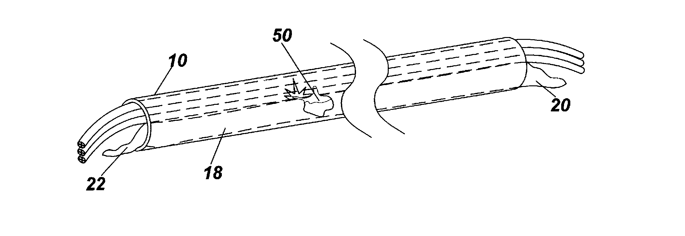
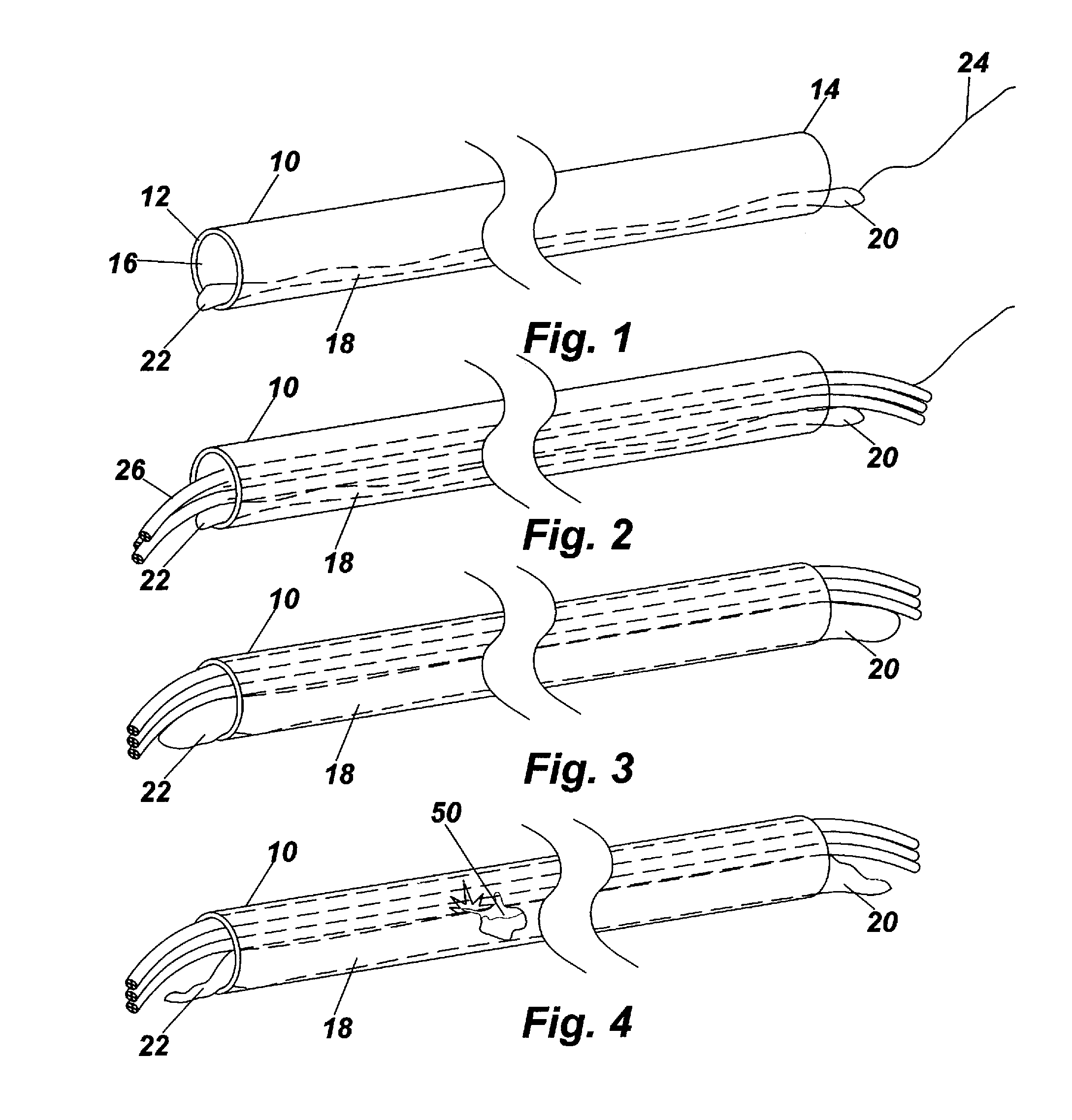
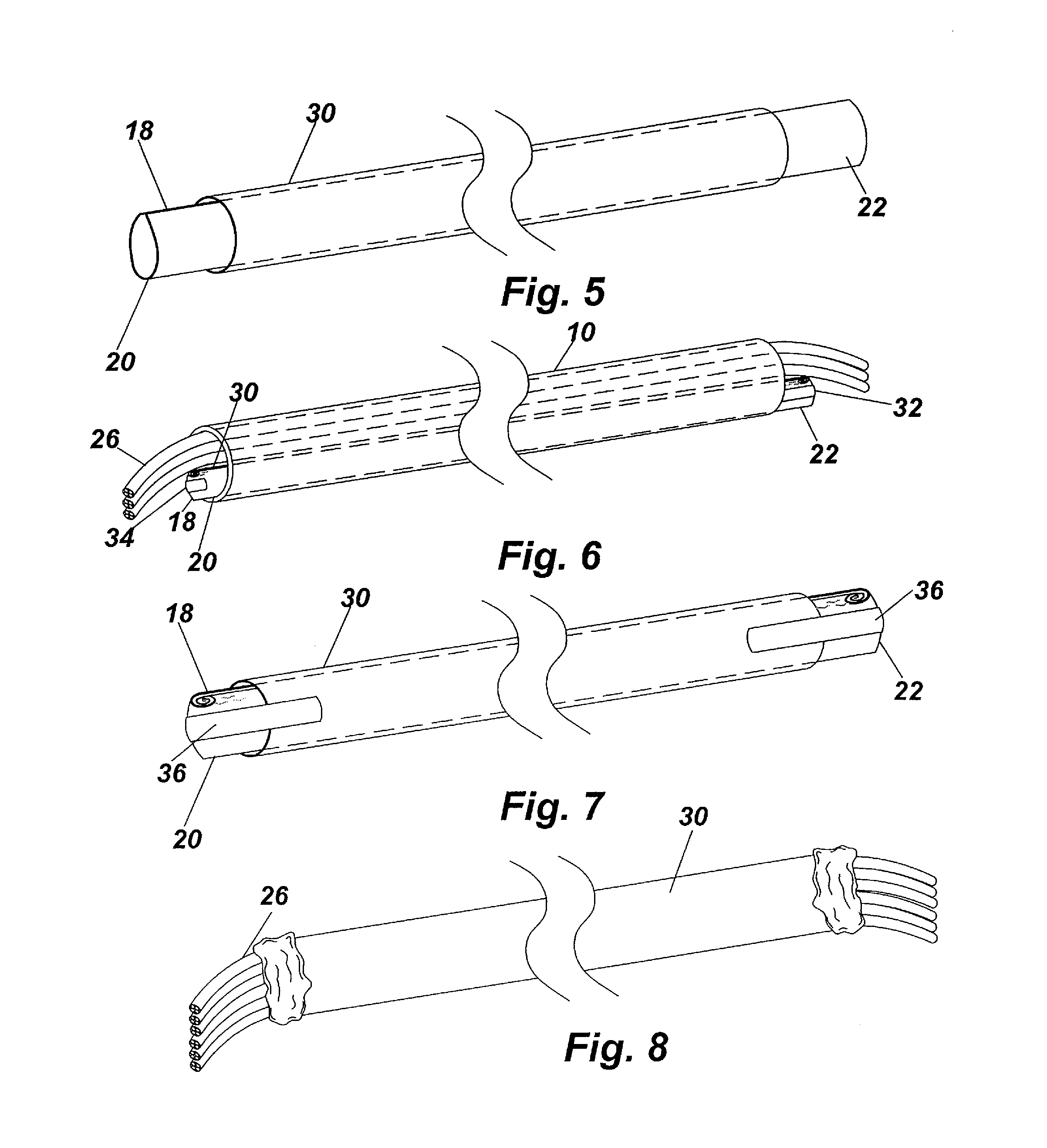
[0039]The present invention relates to a unique technique or method of extinguishing electrical fires and suppressing the spread of electrical fires. This unique technique utilizes a fire suppressant or compositions thereof in an amount sufficient to extinguish an electrical fire and suppress the spread of the electrical fire. The present invention utilizes fire suppressant or compositions thereof, such as, for example, biodegradable, super absorbent, aqueous based polymers. Examples of these polymers are: cross-linked modified polyacrylamides / potassium acrylate or polyacrylamides / sodium acr...


PUM


Abstract

A method and device for suppressing an electrical fire within an electrical wire carrying conduit. The device is a flexible receptacle containing an admixture of super absorbent polymer and water having substantially superior fire suppression and extinguishing properties that does not provide an electrically conductive environment. The receptacle is drawn though a conduit either before or after wires have been placed in the conduit, and the filled with the admixture. A sleeve may be placed over the receptacle to prevent breaching of the receptacle during installation. Once the receptacle and admixture is positioned within the conduit, should arcing or a buildup of heat occur, the receptacle will rupture and the admixture will cover the specific area. These particular properties and ratios of the admixture will enable electrical fires to be extinguished more rapidly and not flare back up. The admixture further encapsulates noxious and toxic gases associated with electrical fires.

Description

RELATED APPLICATIONS[0001]In accordance with 37 C.F.R. 1.76, a claim of priority is included in an Application Data Sheet filed concurrently herewith. Accordingly, the present invention is a continuation-in-part of U.S. patent application Ser. No. 14 / 045,451, entitled “METHOD AND DEVICE FOR SUPPRESSING ELECTRICAL FIRES IN UNDERGROUND CONDUIT”, filed Oct. 3, 2013, which claims priority to U.S. Provisional Patent Application No. 61 / 755,237, entitled “DEVICE FOR SUPPRESSING ELECTRICAL CONDUIT FIRES”, filed Jan. 22, 2013. The contents of which the above referenced application is incorporated herein by reference.FIELD OF THE INVENTION[0002]This invention relates to the field of fire prevention, and more particularly to a device for placement within a conduit for dispersion of a fire suppressant should an electrical fire within the conduit occur.BACKGROUND OF THE INVENTION[0003]In many cities the utilities are located beneath the surface of the earth, usually beneath the surface of the st...

Claims


Application Information

Patent Timeline
Patent Type & Authority Applications(United States)
IPC IPC(8): A62C3/16
CPCA62C3/16A62C35/10
Inventor CORDANI, PETER
Owner REGER MICHAEL L
Why Eureka
Try Eureka