Maximum Power Point Tracking for Solar Panels

a solar panel and maximum power point technology, applied in the direction of d electrical apparatus, ac network circuit arrangement, etc., can solve the problems of reducing accuracy and efficiency, residential solar panel shading from surrounding trees, and high cost of fossil fuel extraction and processing

Active Publication Date: 2014-10-16
VIRGINIA TECH INTPROP INC
View PDF3 Cites 15 Cited by
  • Summary
  • Abstract
  • Description
  • Claims
  • Application Information

AI Technical Summary

Benefits of technology

[0007]It is therefore an object of the present invention to provide MPPT control to a plurality of

Problems solved by technology

Increased difficulty and cost of obtaining and processing fossil fuels as well as concern over pollution caused by their use has increased interest in alternative sources of power, especially from so-called renewable resources such as hydroelectric power, wind-powered generators and solar power collection panels, generally referred to simply as solar panels.
However, such residential installations o

Method used


Image

  • Maximum Power Point Tracking for Solar Panels
  • Maximum Power Point Tracking for Solar Panels
  • Maximum Power Point Tracking for Solar Panels

Examples


Embodiment Construction

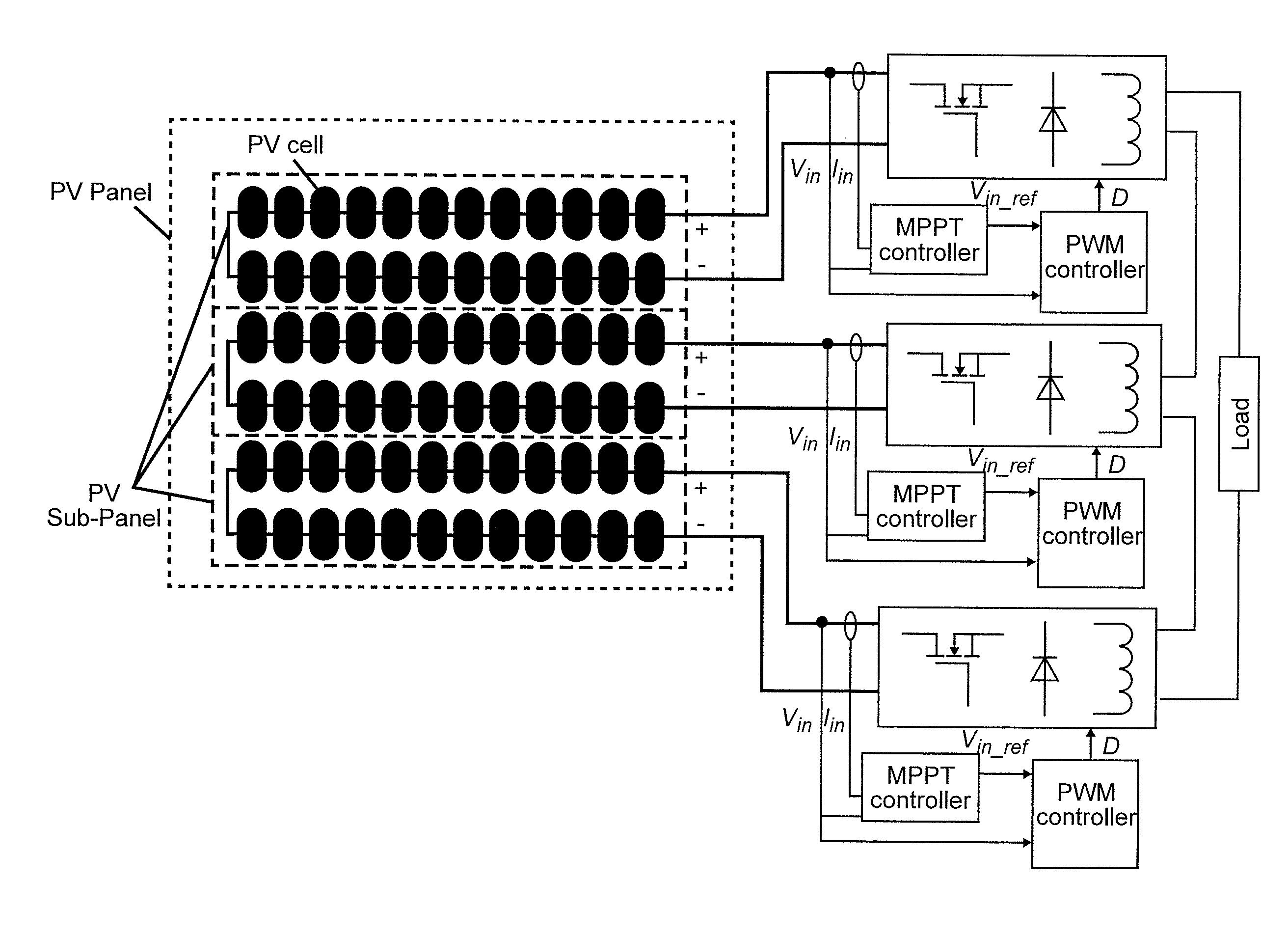
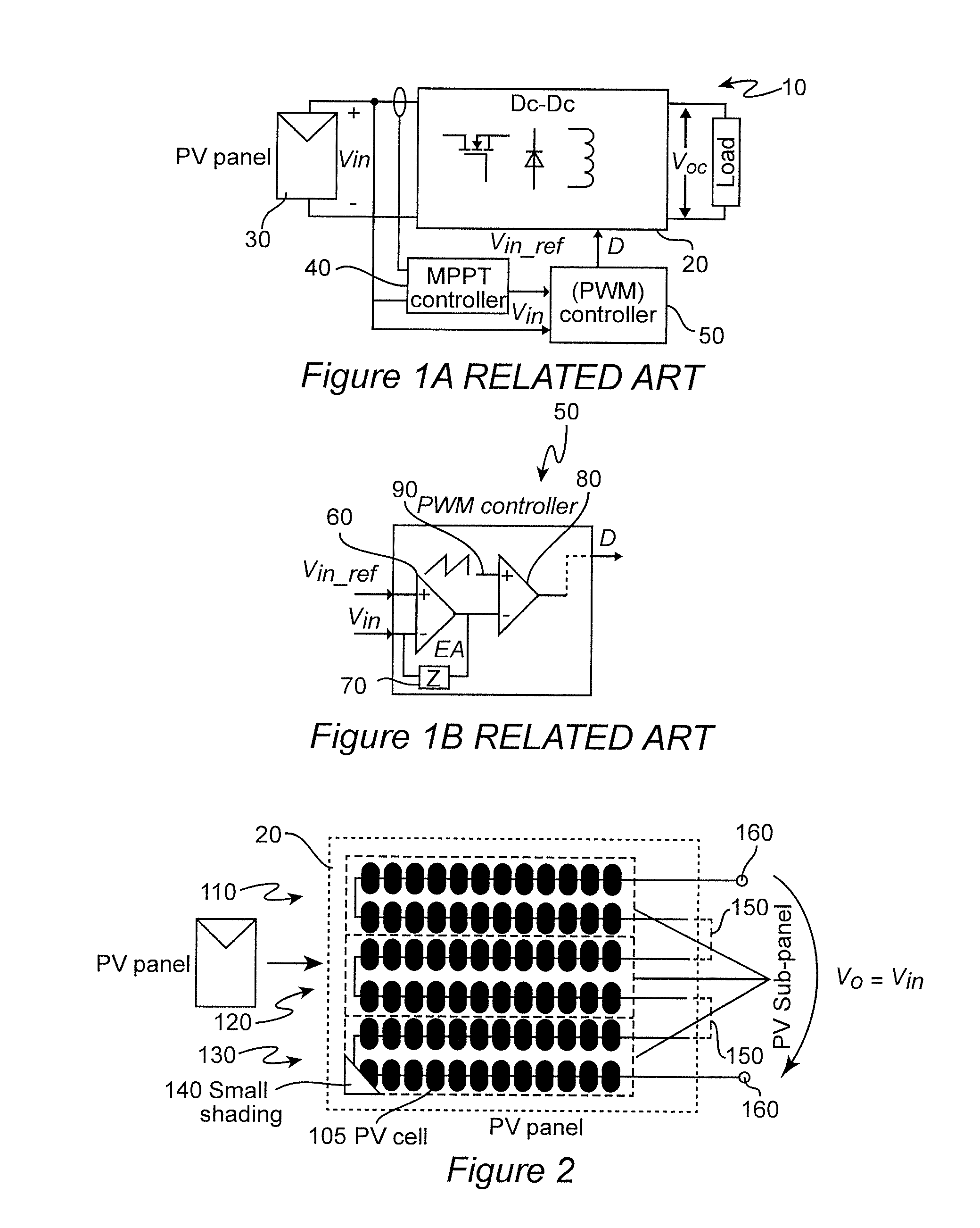
[0021]Referring now to the drawings, and more particularly to FIGS. 1A and 1B, there is shown a high-level schematic diagram depicting and arrangement 10 for using of a power converter 20 of arbitrary topology for applying MPPT tracking control to a PV cell or an array 30 of PV cells of arbitrary extent. It should be understood that FIGS. 1A and 1B are arranged to facilitate an understanding of the invention and its underlying principles and, while the invention is not included in the depiction of FIGS. 1A and 1B, no portion of FIG. 1A or 1B is admitted to be prior art in regard to the present invention and, therefore, these Figures are labeled as “Related Art” in the drawings.

[0022]In the following discussion, use of a buck converter controlled by a pulse width modulation (PWM) controller for the buck converter will be described since the simplicity of both the buck converter and the PWM converter will facilitate a conveyance of an understanding of the invention sufficient to the p...


PUM


Abstract

Approximately one-half of the loss of delivered power from a solar panel having photovoltaic (PV) cells connected in series to form sub-panels due to shading is recovered at low hardware cost by connecting sub-panels in series and providing maximum power point tracking control in common for the series connected sub-panels such that the respective sub-panels produce equal voltages even in the presence of shading of a portion of one or more sub-panels. By doing so, the input voltage of respective power converters which control the voltage at which each sub-panel is operated can be placed close to the maximum power point of each sub-panel regardless of shading and maximum total power harvested even though the respective sub-panels are not operated at optimum voltages.

Description

CROSS-REFERENCE TO RELATED APPLICATIONS[0001]This application claims benefit of priority of U.S. Provisional Application 61 / 811,980, filed Apr. 15, 2013, which is hereby incorporated by reference in its entirety.FIELD OF THE INVENTION[0002]The present invention generally relates to solar power collection panels and, more particularly, to maximizing harvested power from a solar power collection panel that is subject to partial shading.BACKGROUND OF THE INVENTION[0003]Increased difficulty and cost of obtaining and processing fossil fuels as well as concern over pollution caused by their use has increased interest in alternative sources of power, especially from so-called renewable resources such as hydroelectric power, wind-powered generators and solar power collection panels, generally referred to simply as solar panels. Of these possible power sources, solar panels involves the least expensive infrastructure and initial capital expense and are most easily scalable for use by private...

Claims


Application Information

Patent Timeline
IPC IPC(8): H02J1/06
CPCH02J1/06H02J2300/26H02J3/381Y02E10/56H02J3/46
Inventor WU, XINKEWANG, ZIJIANLEE, FRED C.WANG, FENG
Owner VIRGINIA TECH INTPROP INC
Why Eureka
Try Eureka