Method of manufacturing a composite material including a thermoplastic coated reinforcing element

a technology of thermoplastic coating and composite materials, applied in the direction of wind motor components, non-positive displacement fluid engines, rotorcraft, etc., can solve the problems of poor inter-laminar or through thickness, mechanical properties in comparison to the corresponding in-plane properties, and limit the use of such materials for certain applications, so as to reduce the time, cost and/or practicality of operation.

Active Publication Date: 2014-10-16
ROLLS ROYCE PLC
View PDF4 Cites 1 Cited by
  • Summary
  • Abstract
  • Description
  • Claims
  • Application Information

AI Technical Summary

Benefits of technology

[0036]The step of through-thickness reinforcing the base material may include inserting a plurality of reinforcing elements each of which is coated with a corresponding thermoplastic layer such that during the step of curing each thermoplastic layer forms a corresponding interphase zone surrounding the corresponding reinforcing element. A typical composite component which is to be formed with through-thickness reinforcement may comprise many thousands of through-thickness reinforcing fibres. Thus, inserting at least some of the reinforcing fibres simultaneously reduces the time, cost and / or practicality of the operation.

Problems solved by technology

A known problem with laminated composite materials is their poor inter-laminar, or through-thickness, mechanical properties in comparison to the corresponding in-plane properties.
Such low inter-laminar strength and fracture toughness can constrain the design of composite parts and may even limit the use of such materials for certain applications.
Such matrix materials are generally significantly more expensive than conventional matrix materials, often have poor high temperature properties and may still not provide a sufficient increase in fracture toughness.
Although the presence of the through-thickness reinforcing fibres increases the intra-laminar strength of the composite material, their presence in the structure can introduce an altogether different weakness.
Naturally, this increases the time and cost of manufacturing the composite material and, by extension, the resulting completed component.
Furthermore, in itself this solution does not prevent cracks forming around the reinforcing fibres.
A further problem with the conventional z-pinning process is that the fibrous reinforcing pins can split or fracture during insertion as a result of the need to force the pins through the densely compacted fibre layers of the laminate and / or through the resin (for example where the fibres are pre-impregnated with resin).
This can reduce the effectiveness of the presence of the reinforcing pins.
Thus, inserting at least some of the reinforcing fibres simultaneously reduces the time, cost and / or practicality of the operation.

Method used


Image

  • Method of manufacturing a composite material including a thermoplastic coated reinforcing element
  • Method of manufacturing a composite material including a thermoplastic coated reinforcing element
  • Method of manufacturing a composite material including a thermoplastic coated reinforcing element

Examples


Embodiment Construction

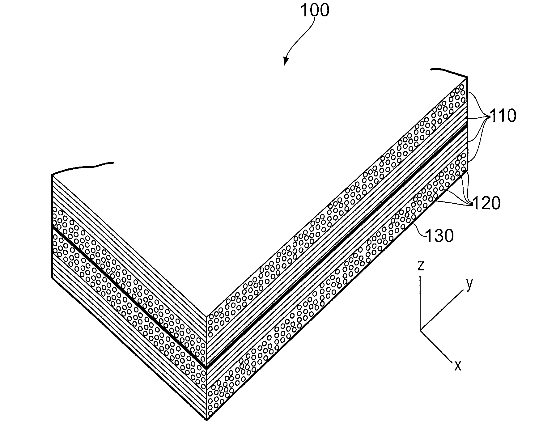
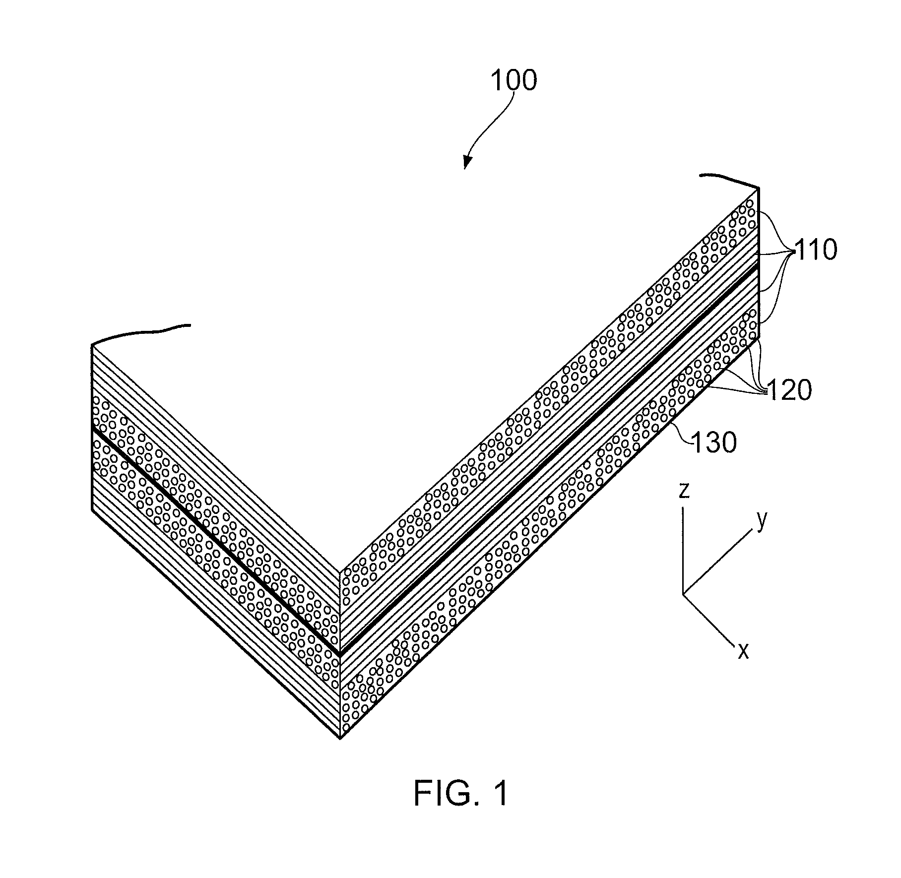
[0054]FIG. 1 shows an example of a laminated composite material 100 comprising a plurality of fibre layers 110. Each of the fibre layers 110 comprises a plurality of uni-directionally aligned fibres 120 held within a matrix material 130. The matrix material 130 is cured so that the fibre layers 110 and the matrix material consolidate to form the solid composite material 100.

[0055]It can be seen in the example of FIG. 1 that alternate fibre layers 110 are laid up approximately perpendicular to one another. In alternative arrangements, the fibre layers 110 may comprise fibres having other orientations. The relative fibre orientation of each of the layers 110 together with the quantity of fibre layers 110 is determined by the design loads to which the finished component is to be subjected.

[0056]In FIG. 1 the fibre layers 110 of one orientation lie along the X direction while those of the alternate orientation lie along the Y direction. Were the composite material 100 of FIG. 1 to inclu...


PUM

PropertyMeasurementUnit
melting temperatureaaaaaaaaaa
temperatureaaaaaaaaaa
thicknessaaaaaaaaaa

Abstract

A method of through-thickness reinforcing a laminated material is disclosed, in which a reinforcing element is coated with a thermoplastic layer. The reinforcing element is inserted into a base material, and a matrix material, such as a polymeric, is included in the base material. The combination is then cured, or heated, such that the thermoplastic layer and the matrix material diffuse into each other, thereby forming an interphase region around the reinforcing element. This interphase region helps to prevent cracks from propagating from the reinforcing element.

Description

CROSS-REFERENCE TO RELATED APPLICATIONS[0001]This application is based upon and claims the benefit of priority from British Patent Application Number 1306481.1 filed 10 Apr. 2013, the entire contents of which are incorporated by reference.BACKGROUND OF THE INVENTION[0002]1. Field of the Disclosure[0003]This invention relates to a method of manufacturing a composite material. In particular, the invention relates to a method of manufacturing a composite material including at least one reinforcing element.[0004]2. Description of the Related Art[0005]Laminated composite materials, in which reinforcing fibres are held within a polymeric matrix, are extensively used in many engineering applications. Such materials can generally provide a higher strength and stiffness per unit weight than conventional metallic materials. This makes such composite materials advantageous for weight sensitive applications, such as those in the field of aerospace.[0006]A known problem with laminated composite ...

Claims


Application Information

Patent Timeline
Patent Type & Authority Applications(United States)
IPC IPC(8): F01D5/14B05D1/02B05D1/18B29C70/40
CPCF01D5/147B05D1/18B05D1/02B29C70/40B29C70/887B29C70/24B29L2031/7504B29K2101/12B29L2031/08Y10T428/24331
Inventor JEVONS, MATTHEW PAUL
Owner ROLLS ROYCE PLC
Why Eureka
Try Eureka