Method and apparatus for detecting defects in freeform fabrication

Active Publication Date: 2014-10-16
ARCAM AB
View PDF4 Cites 116 Cited by
  • Summary
  • Abstract
  • Description
  • Claims
  • Application Information

AI Technical Summary

Benefits of technology

[0005]An object of the invention is to provide a method and apparatus for increasing the reliability of the defect detection and thereby decreasing the

Problems solved by technology

A problem with this defect detection method is that not all of the irregularities that are detected will cause a real defect in the thr

Method used


Image

  • Method and apparatus for detecting defects in freeform fabrication
  • Method and apparatus for detecting defects in freeform fabrication
  • Method and apparatus for detecting defects in freeform fabrication

Examples


Embodiment Construction

[0042]To facilitate the understanding of this invention, a number of terms are defined below. Terms defined herein have meanings as commonly understood by a person of ordinary skill in the areas relevant to the present invention. Terms such as “a”, “an” and “the” are not intended to refer to only a singular entity, but include the general class of which a specific example may be used for illustration. The terminology herein is used to describe specific embodiments of the invention, but their usage does not delimit the invention, except as outlined in the claims.

[0043]The term “three-dimensional structures” and the like as used herein refer generally to intended or actually fabricated three-dimensional configurations (e.g. of structural material or materials) that are intended to be used for a particular purpose. Such structures, etc. may, for example, be designed with the aid of a three-dimensional CAD system.

[0044]The term “electron beam” as used herein in various embodiments refer...


PUM

PropertyMeasurementUnit
Timeaaaaaaaaaa
Timeaaaaaaaaaa
Poweraaaaaaaaaa

Abstract

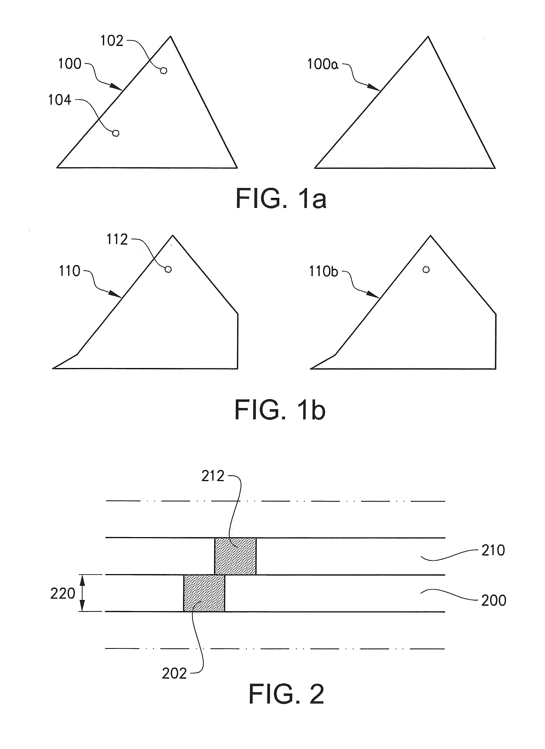
A method for detecting defects in three-dimensional articles. Providing a model of said article. Providing a first powder layer on a substrate, directing an energy beam over said substrate causing said first powder layer to fuse in selected locations forming a first cross section of said three-dimensional article, providing a second powder layer on said substrate, directing the energy beam over said substrate causing said second powder layer to fuse in selected locations to form a second cross section of said three-dimensional article. A first and second image of a first and second fusion zone of said first powder layer respectively is captured. Comparing said first and second images with corresponding layers in said model. Detecting a defect in the three-dimensional article if a deviation in said first image with respect to said model is at least partially overlapping a deviation in said second image with respect to said model.

Description

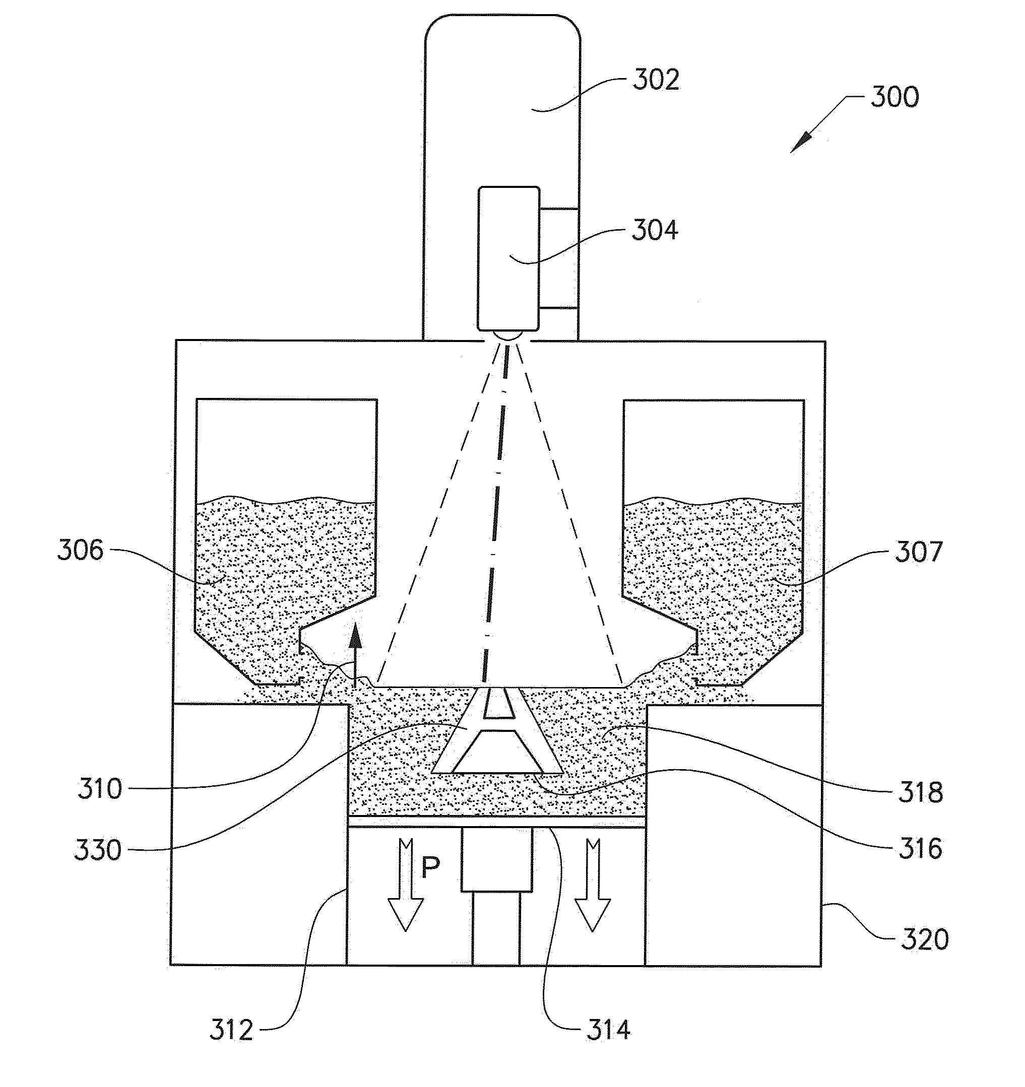
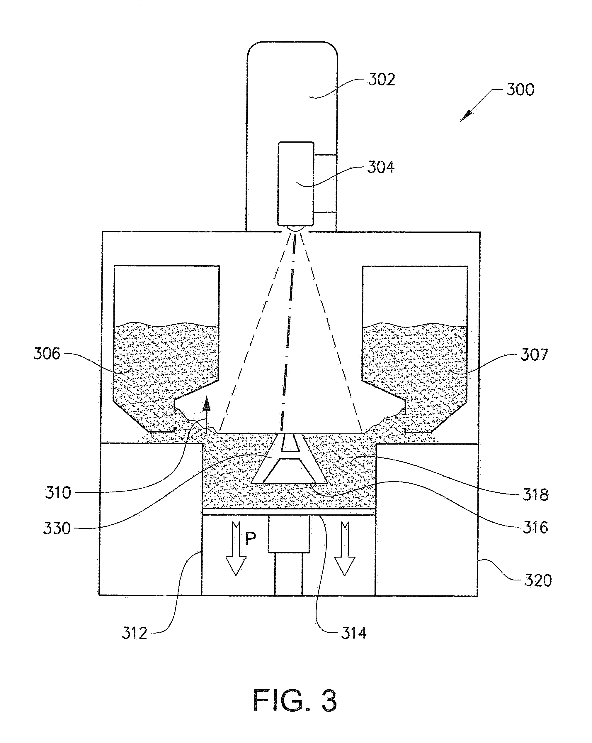
TECHNICAL FIELD[0001]The present invention relates to a method for detecting defects according to the preamble of claim 1 and to an apparatus for detecting defects according to the preamble of claim 9.BACKGROUND OF THE INVENTION[0002]Freeform fabrication or additive manufacturing is a method for forming three-dimensional articles through successive fusion of chosen parts of powder layers applied to a worktable. A method and apparatus according to this technique is disclosed in US 2009 / 0152771.[0003]Such an apparatus may comprise a work table on which said three-dimensional article is to be formed, a powder dispenser, arranged to lay down a thin layer of powder on the work table for the formation of a powder bed, a ray gun for delivering energy to the powder whereby fusion of the powder takes place, elements for control of the ray given off by the ray gun over said powder bed for the formation of a cross section of said three-dimensional article through fusion of parts of said powder...

Claims


Application Information

Patent Timeline
IPC IPC(8): B22F3/105
CPCB22F3/1055B29C67/0077C22C21/00C22C19/07B22F3/15C22C14/00B22F2003/1056B32B15/01B32B15/012B32B15/013C22C38/00G01N21/9515B29C64/153Y02P10/25B22F10/28B22F12/52B22F10/38B22F12/90B22F10/85
Inventor LJUNGBLAD, ULRIC
Owner ARCAM AB
Why Eureka
Try Eureka