Memory system

a memory system and memory technology, applied in the field of memory, can solve the problems of increased synchronization overhead, increased time cost for executing a mechanism, increased synchronization overhead, etc., and achieve the effect of lower latency of the first memory devi

Inactive Publication Date: 2014-10-16
SAMSUNG ELECTRONICS CO LTD
View PDF6 Cites 12 Cited by
  • Summary
  • Abstract
  • Description
  • Claims
  • Application Information

AI Technical Summary

Benefits of technology

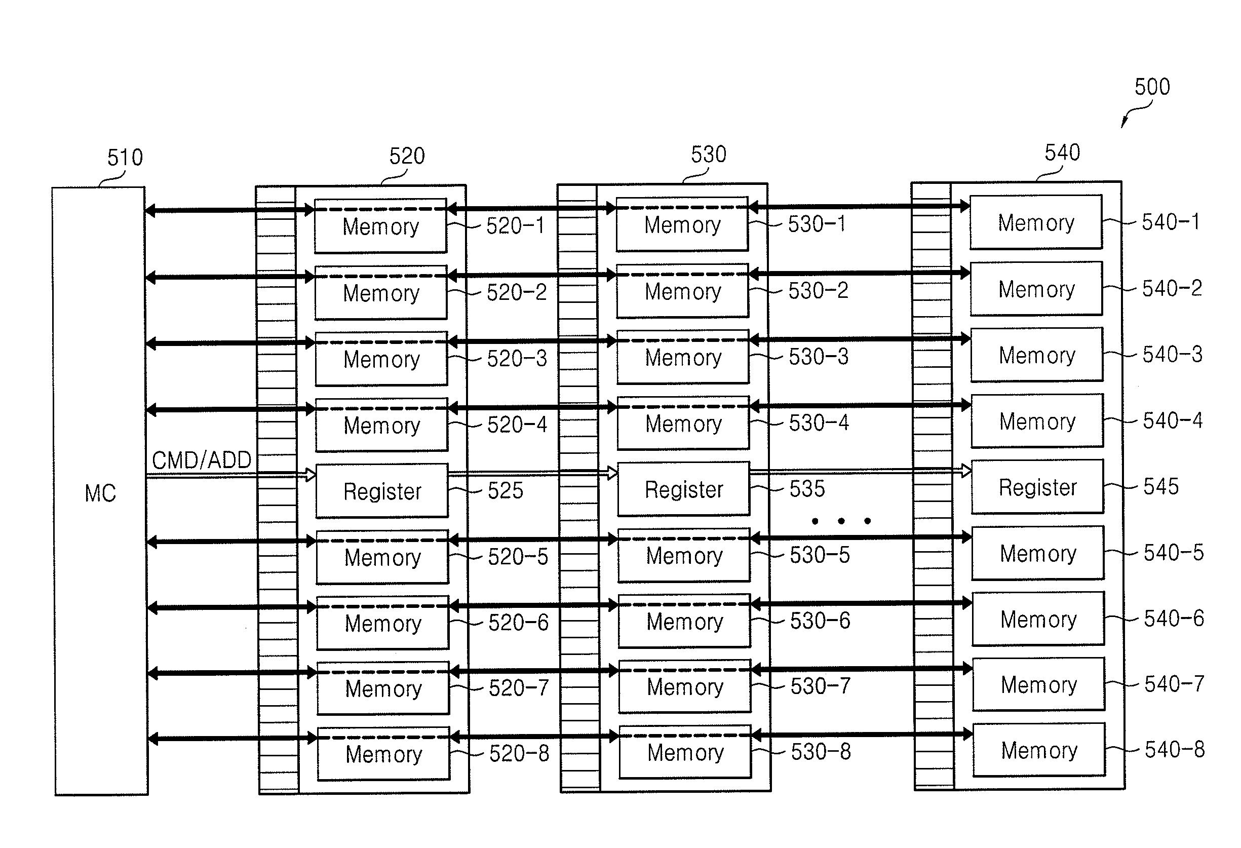
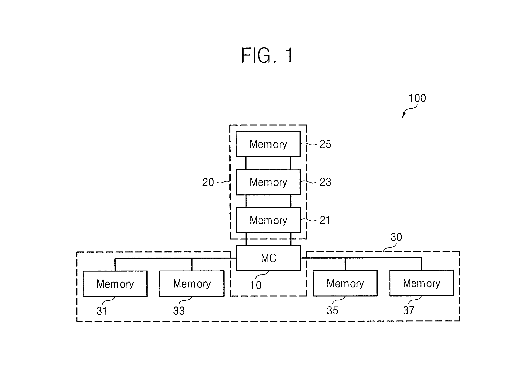
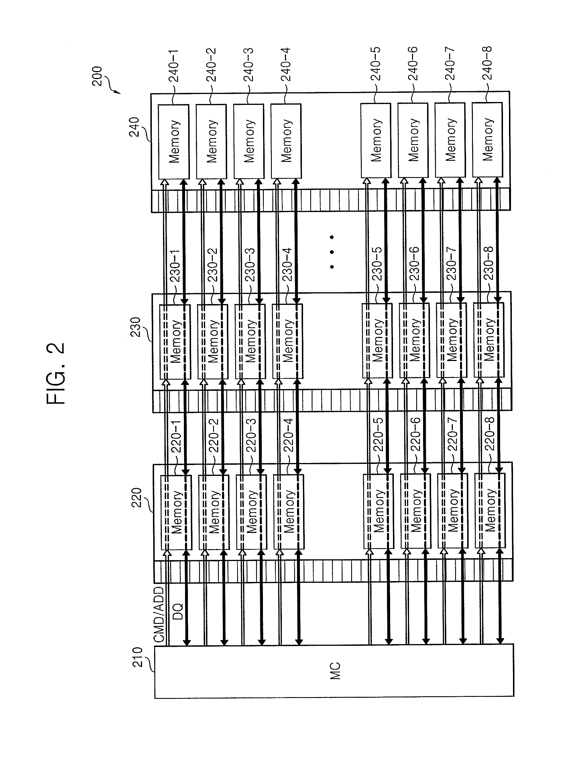
[0008]Also, a latency of the first memory device is lower than a latency of the second memory device, when the first memory device is physically closer to the memory controller than the second memory device.
[0009]Also, a latency of the first memory device is lower than a latency of the second memory device, when the first memory device is connected to the memory controller through a vertical electrical connector and the second memory device is connected to the memory controller through a wire bond.
[0010]Also, a latency of the first memory device is lower than a latency of the second memory device, when the error correction capability of the first memory device is lower than the error correction capability of the second memory device.
[0011]Also, a latency of the first memory device is lower than a latency of the second memory device, when a memory supply voltage of the first memory device is higher than a memory supply voltage of the second memory device.

Problems solved by technology

If the processing unit is a type which performs multi-thread operations, synchronization overhead may increase.
One type of synchronization overhead involves an increased time cost for executing a mechanism to regulate access of data stored in the memory devices.
The increased time cost may be especially pronounced in a system in which memory devices are to be controlled separately.

Method used


Image

  • Memory system
  • Memory system
  • Memory system

Examples


Embodiment Construction

[0037]Example embodiments are described more fully hereinafter with reference to the accompanying drawings; however, they may be embodied in different forms and should not be construed as limited to the embodiments set forth herein. Rather, these embodiments are provided so that this disclosure will be thorough and complete, and will fully convey exemplary implementations to those skilled in the art.

[0038]In the drawing figures, the dimensions of layers and regions may be exaggerated for clarity of illustration. It will also be understood that when a layer or element is referred to as being “on” another layer or substrate, it can be directly on the other layer or substrate, or intervening layers may also be present. Further, it will be understood that when a layer is referred to as being “under” another layer, it can be directly under, and one or more intervening layers may also be present. In addition, it will also be understood that when a layer is referred to as being “between” t...


PUM


Abstract

A memory system includes a memory controller to control a first memory device and a second memory device. The first and second memory devices are different in terms of at least one of physical distance from the memory controller, a manner of connection to the memory controller, error correction capability, or memory supply voltage. The first and second memory devices also have different latencies.

Description

CROSS-REFERENCE TO RELATED APPLICATION[0001]Korean Patent Application No. 10-2013-0040123, filed on Apr. 11, 2013, and entitled, “Memory System,” is incorporated by reference herein in its entirety.BACKGROUND[0002]1. Field[0003]One or more embodiments described herein relate to a memory.[0004]2. Description of the Related Art[0005]A variety of memory systems have been developed. One type of memory system includes a plurality of memory devices, a memory controller, and a processing unit. The processing unit may be a central processing unit (CPU) or a graphic processing unit (GPU). If the processing unit is a type which performs multi-thread operations, synchronization overhead may increase.[0006]One type of synchronization overhead involves an increased time cost for executing a mechanism to regulate access of data stored in the memory devices. The increased time cost may be especially pronounced in a system in which memory devices are to be controlled separately. In order to separat...

Claims


Application Information

Patent Timeline
Patent Type & Authority Applications(United States)
IPC IPC(8): G06F13/16
CPCG06F13/1657G06F13/161G06F13/1694G11C7/10
Inventor CHUNG, HOI JUKIM, SU APARK, CHUL WOOYU, HAK SOOYOUN, JAE YOUNLEE, JUNG BAECHOI, HYO JIN
Owner SAMSUNG ELECTRONICS CO LTD
Why Eureka
Try Eureka