Peeling Machine

a technology of peeling machine and feed roller, which is applied in the direction of turning machine, turning apparatus, manufacturing tools, etc., can solve the problems of reducing working efficiency, difficulty in rapid opening/close of feed roller, and increasing working tim

Active Publication Date: 2014-10-23
DAISHO SEIKI CORP
View PDF4 Cites 8 Cited by
  • Summary
  • Abstract
  • Description
  • Claims
  • Application Information

AI Technical Summary

Benefits of technology

[0009]The present invention is devised in consideration of the above-mentioned problem, and its object is to provide a peeling machine provided with a feed mechanism capable of opening/closing the upper and l...

Problems solved by technology

However, with such configuration, it is difficult to rapidly open/close the feed rollers 201, 202, accurately position the feed rollers 201, 202, and grasp the work with an appropriate grasping force according to the diameter of the work.
Conversely, when the moving speed of the holders is decreased to enable grasping of the work with the appropriate grasping force according to the type of the work, working time increases, lowering the working efficiency.
When the grasping force with r...

Method used


Image

  • Peeling Machine
  • Peeling Machine
  • Peeling Machine

Examples


Embodiment Construction

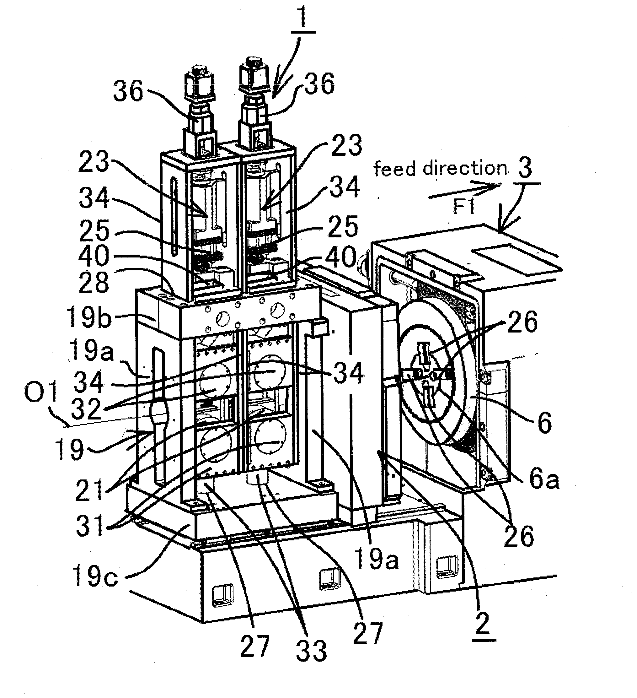
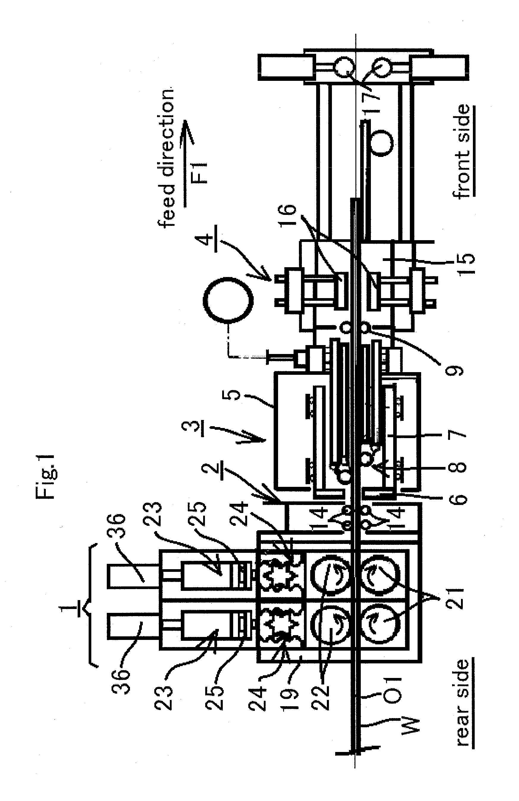
[0029]FIG. 1 to FIG. 7 show a peeling machine according to the present invention, and an embodiment of the present invention will be described below with reference to these drawings.

[0030]FIG. 1 is an overall schematic side view of the peeling machine. For convenience of description, a side of a work feed direction F1 is referred to as “front side” of a machine, a feed mechanism, and the like; the opposite side to the work feed direction F1 is referred to as “rear side” of the machine, the feed mechanism, and the like; the side on which the operator is located (front side in FIG. 1) is referred to as machine-operating side;, and the opposite side to the machine-operating side is referred to as machine-non-operating side, in the following description.

[0031]In FIG. 1, the peeling machine includes a feed mechanism 1, a first guide roller mechanism 2, a machine body 3, and a carriage mechanism 4 in this order from the rear side toward the front side. The machine body 3 has a cutter head...


PUM


Abstract

A peeling machine according to the present invention includes a cutter head and a feed mechanism having upper and lower feed rollers, and the feed mechanism includes a first holder that supports the lower feed roller, a second holder that supports the upper feed roller, a roller opening/closing driving mechanism, a synchronizing mechanism that has a pinion disposed in the same vertical plane as axes of the both feed rollers and first and second racks, and a grasping-force applying cylinder that applies a downward work grasping force to the second holder.

Description

BACKGROUND OF INVENTION[0001]1. Field of the Invention[0002]The present invention relates to a peeling machine for continuously cutting the outer peripheral surface of a round rod-like work, and in particular, to a feed mechanism for feeding the work to a cutter head.[0003]2. Description of the Prior Art[0004]Generally, a peeling machine includes a cutter head that rotates about a substantially horizontal mechanical center line to cut the outer peripheral surface of a round rod-like work, and a feed mechanism that holds the work on the mechanical center line between upper and lower feed rollers and feeds the work to the cutter head.[0005]Japanese Unexamined Patent Publication No. H4 (1992)-226803 discloses various feed mechanisms for conventional peeling machines, and FIG. 8 shows one of the feed mechanisms. In FIG. 8, the feed mechanism includes a pair of upper and lower feed rollers 201, 202 that hold a round rod-like work W therebetween, and holders 203, 204 for supporting the fe...

Claims


Application Information

Patent Timeline
IPC IPC(8): A47J17/16
CPCA47J17/16B23B5/12Y10T83/6497
Inventor YOSHIZURU, SHOJI
Owner DAISHO SEIKI CORP
Why Eureka
Try Eureka