Flexible low modulus photovoltaic building sheathing member

Inactive Publication Date: 2014-10-23
DOW GLOBAL TECH LLC
View PDF2 Cites 15 Cited by
  • Summary
  • Abstract
  • Description
  • Claims
  • Application Information

AI Technical Summary

Benefits of technology

[0018]FIG. 6 shows a system useful for perf

Problems solved by technology

These systems may be complicated, typically do not install like conventional cladding materials (e.g. roofing shingles or siding) and, as a consequence, may be expensive to install.
Also, they may not be visually appealing as they do not look li

Method used


Image

  • Flexible low modulus photovoltaic building sheathing member
  • Flexible low modulus photovoltaic building sheathing member
  • Flexible low modulus photovoltaic building sheathing member

Examples


Example

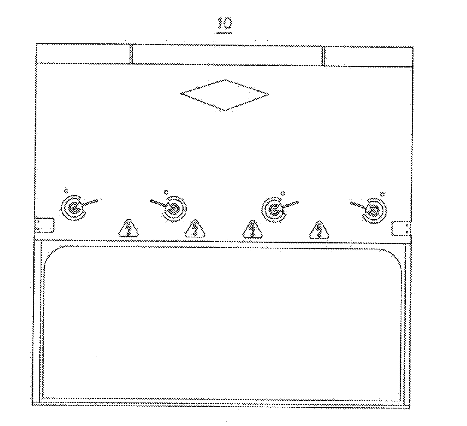
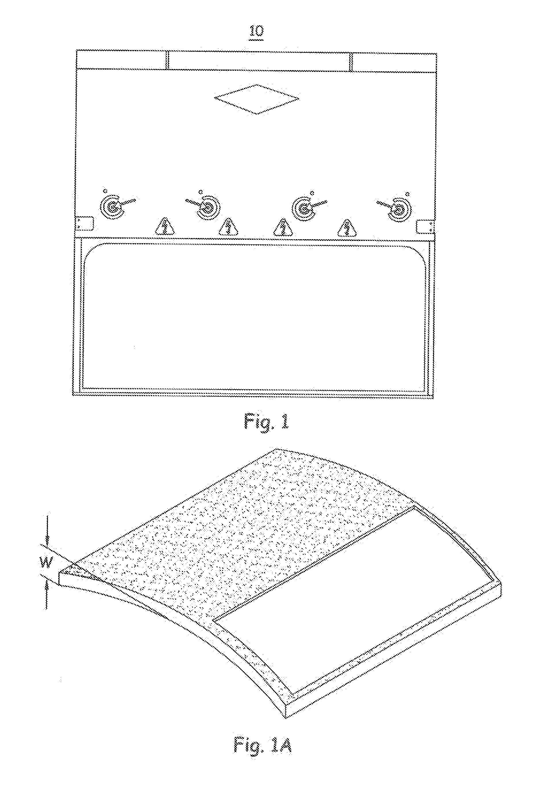
[0019]The present invention relates to an improved photovoltaic device 10 (hereafter “PV device”), as illustrated in FIG. 1, can be described generally as an assembly of a number of components and component assemblies that functions to provide electrical energy when subjected to solar radiation (e.g. sunlight). Of particular interest and the main focus of the present disclosure is an improved PV device 10 that includes at least a multilayered photovoltaic cell assembly 100 (hereafter “MPCA”) joined to a body portion 200. In a preferred embodiment, the PV device is formed by taking the MPCA (and potentially other components and assemblies such as connector components) and forming (e.g. via injection molding) the body portion about at least portions the MPCA. It is contemplated that the relationships (e.g. at least the geometric properties and the material properties) between the components and component assemblies are surprisingly important in solving one or more the issues discussed...


PUM


Abstract

The present invention is premised upon -m improved photovoltaic building sheathing member (“PV device”), more particularly to a flexible low modulus photovoltaic building sheathing member, the member comprising: a flexible photovoltaic cell assembly, a body portion comprised of a body material and connected to a; peripheral edge segment of the photovoltaic cell assembly, wherein the body portion has a cross-sectional area of at least 35 mm2 within 1 cm on at least 95 percent of points along the peripheral edge segment: wherein the body material comprises a composition having a modulus of 5 to 200 MPa between a temperature of −40 to 85° C., with a coefficient of thermal expansion (GTE) below 100×10−6/° C., and the body portion exhibiting a warpage value of less than 15 mm.

Description

[0001]This invention was made with U.S. Government support under contract DE-FC36-07G01754 awarded by the Department of Energy. The U.S. Government has certain rights in this invention.FIELD OF THE INVENTION[0002]The present invention relates to an improved photovoltaic device (“PVD” or “PV Device”), more particularly to an improved flexible photovoltaic device (building sheathing member) with a multilayered photovoltaic cell assembly and a body portion joined at an interface region.BACKGROUND[0003]Efforts to improve PV devices, particularly those devices that are integrated into building structures (e.g. roofing shingles or exterior wail coverings), to be used successfully, should satisfy a number of criteria. The PV device should be durable (e.g. long lasting, sealed against moisture and other environmental conditions) and protected from mechanical abuse over the desired lifetime of the product, preferably at least 10 years, more preferably at least 25 years. The device should be ...

Claims


Application Information

Patent Timeline
IPC IPC(8): H01L31/042
CPCH01L31/0422H02S20/25Y02B10/10Y02E10/50
Inventor FENG, JIEKAUFFMANN, KEITH L.YANG, KWANHOLIU, HUAZAWISZA, JEFFREY D.LOPEZ, LEONARDO C.
Owner DOW GLOBAL TECH LLC
Why Eureka
Try Eureka