Compound Optical Combiner

a combiner and optical technology, applied in the field of optical combiners, can solve the problems of large loss, small power loss, signal distortion, etc., and achieve the effects of minimizing insertion loss, large bandwidth, and simple fabrication

Active Publication Date: 2014-10-23
MITSUBISHI ELECTRIC CORP +1
View PDF4 Cites 5 Cited by
  • Summary
  • Abstract
  • Description
  • Claims
  • Application Information

AI Technical Summary

Benefits of technology

[0007]It is an object of some embodiments of the invention to a system for combining optical signals white minimizing insertion loss. It is a further object of some embodiments of the invention to provide an optical combiner that has a large bandwidth and is simple to fabricate.

Problems solved by technology

Wavelength combiners are typically narrow hand, which can cause signal distortion.
The wavelength combiners theoretically provide small power loss, but in practice the loss is much larger.
The precise control of dimensions of the wavelength combiners is difficult and small error in the dimensions of the combiner can lead to a large insertion loss.

Method used


Image

  • Compound Optical Combiner
  • Compound Optical Combiner
  • Compound Optical Combiner

Examples


Embodiment Construction

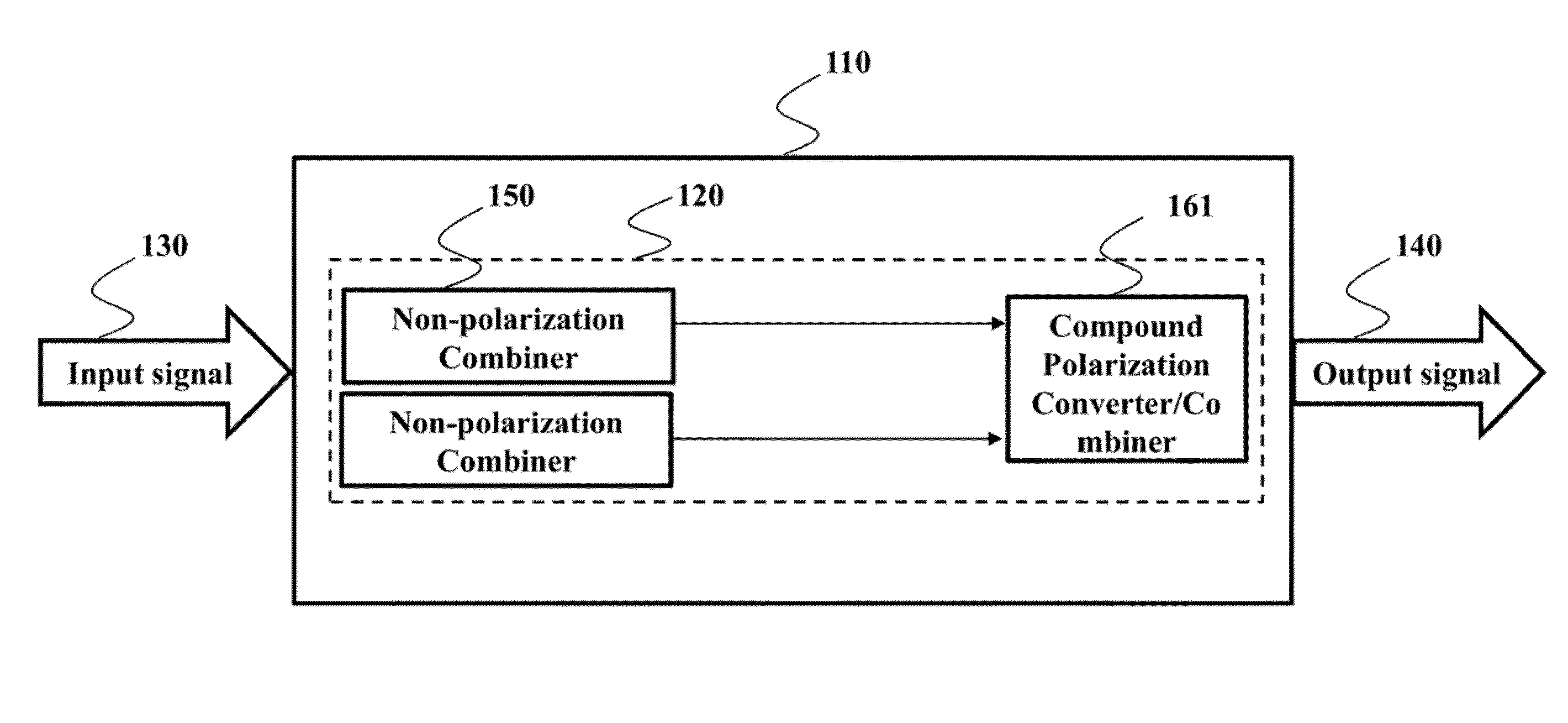
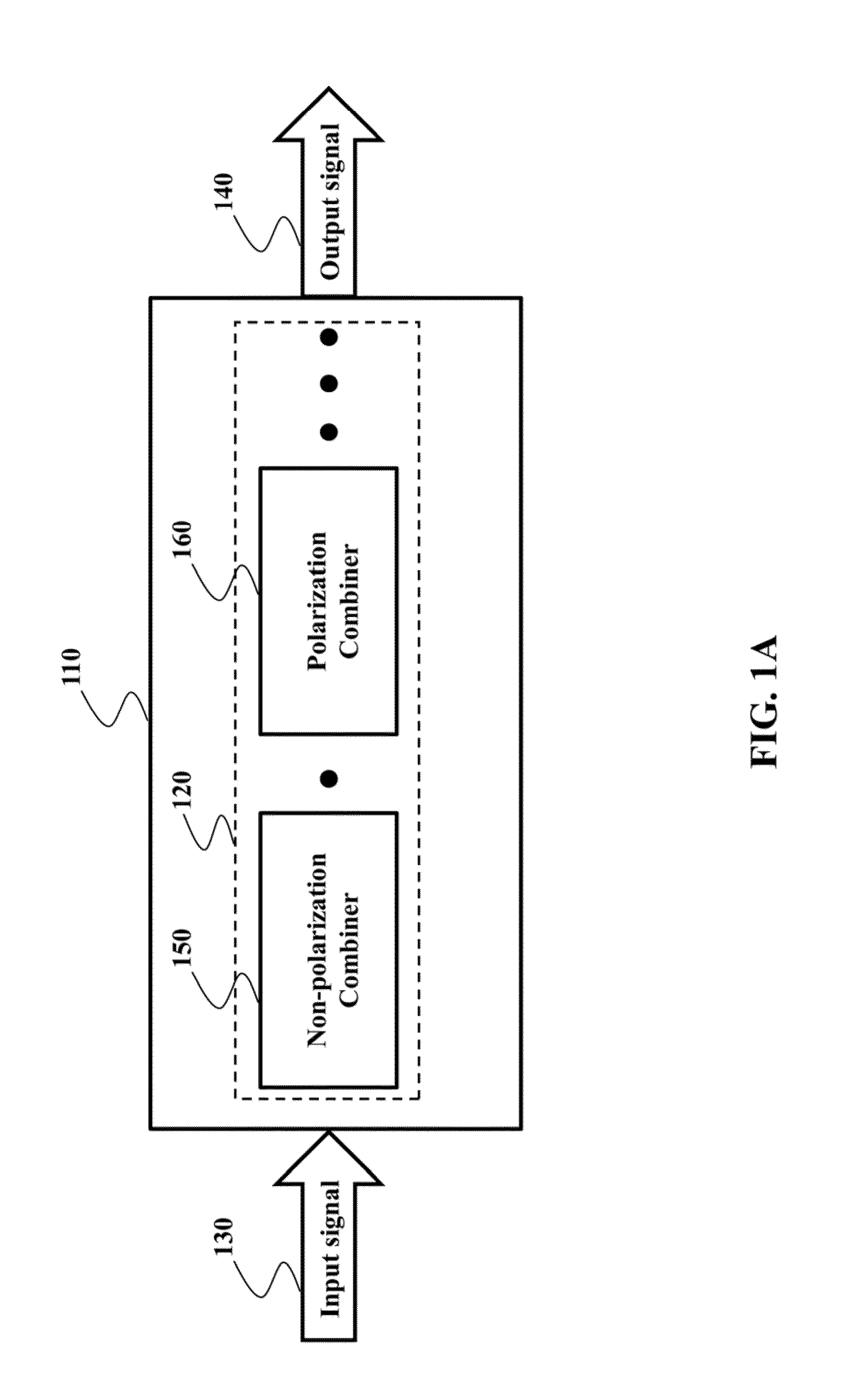
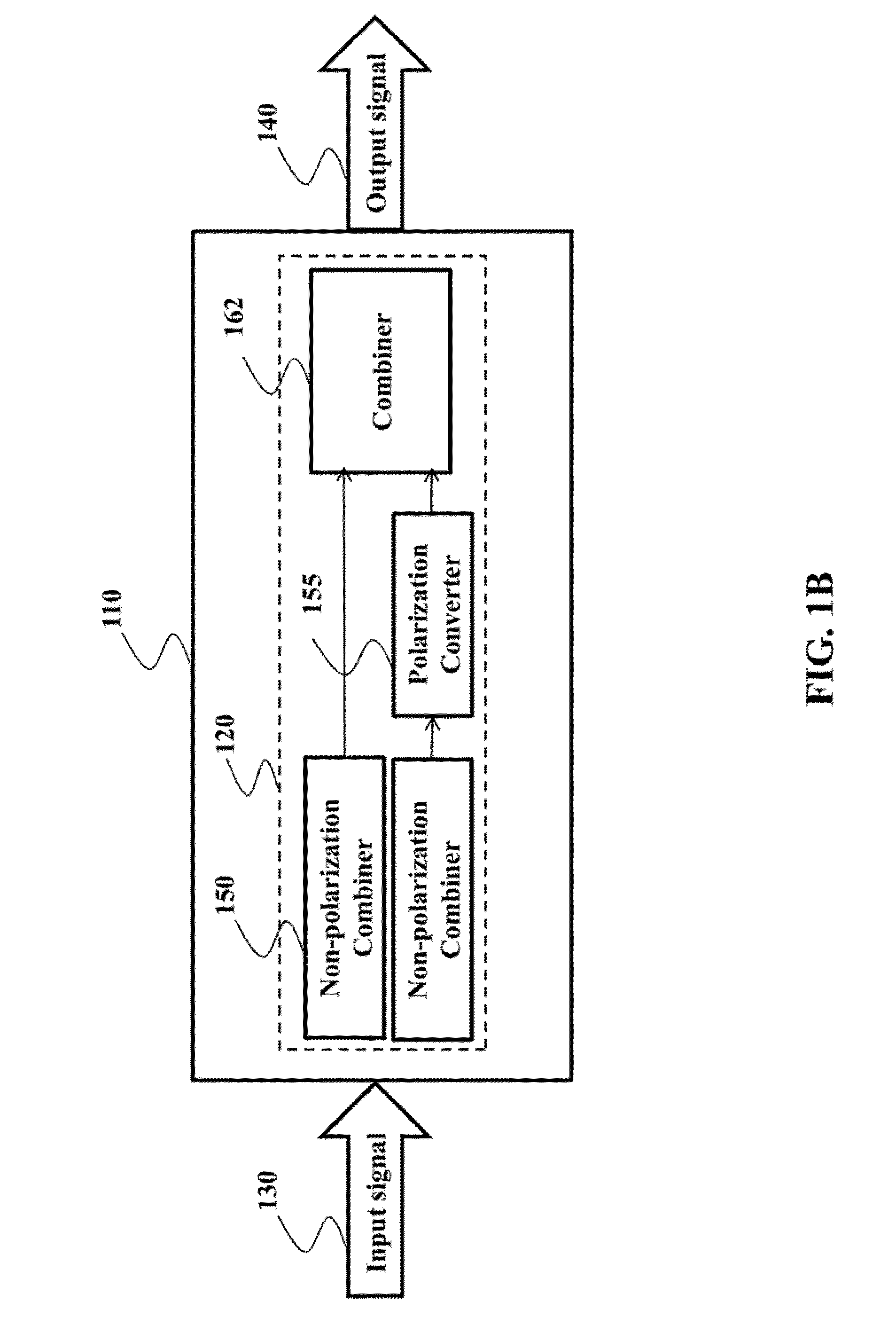
[0023]Some embodiments of die invention provide an optical combiner for multiple optical signals that minimizes insertion loss, and maximizes bandwidth. Some embodiments take advantage from the fact that, polarization multiplexing is typically not used when communicating data optically. In other words, each optical signal has a single polarization. Similarly, optical sources, e.g., lasers oscillate with the same polarization, e.g., in transverse electric (IF) modes. In addition, optical signals in a single mode fiber can be of any polarization. There is no requirement for relative polarizations among optical signals.

[0024]Such realizations and recognitions enable the design of a compound optical combiner using both polarization and non-polarization combiners. Advantageously, polarization combiner eliminates inherent loss when compared with power only combiners. In addition, polarization combiners reduce the requirement of wavelength characteristics and double wavelength separation a...


PUM


Abstract

A compound optical combiner for combining multiple optical signals includes a set of combiners. The set of combiners includes at least one polarization combiner optically connected to at least one non-polarization combiner. The non-polarization combiner combines a first set of input signals while preserving a polarization of each input signal in the first set of signals. The polarization combiner combines a second set of input signals while converting the polarization of at least one input signal in the second set of signals.

Description

FIELD OF THE INVENTION[0001]This invention relates generally to optical combiners, and more particularly to compound optical combiners for combining multiple optical signals.BACKGROUND OF THE INVENTION[0002]in optical communication systems, such as 40 G bits per second (b / s) or 100 G b / s Ethernet for distances less than 40 km, data rates and bandwidth are required to be very high, and the size and cost of transceivers are expected to be very low. To reduce the cost, in many cases, multiple optical signals of different wavelengths are combined into a single optical fiber. By combining several signals, the capacity of optical communications is increased.[0003]There are two types of optical combiners, i.e., power combiners and wavelength combiners. Multimode interference (MMI) based couplers are commonly used as power combiners for combining multiple optical signals of different wavelengths. At the input side of the MMI coupler, a number of waveguide ports are used to guide multiple in...

Claims


Application Information

Patent Timeline
Patent Type & Authority Applications(United States)
IPC IPC(8): G02B6/27
CPCG02B6/2773
Inventor KOJIMA, KEISUKEWANG, BINGNANKOIKE-AKINO, TOSHIAKINISHIKAWA, SATOSHIYAGYU, EIJI
Owner MITSUBISHI ELECTRIC CORP
Why Eureka
Try Eureka