

Cutting insert, cutting tool, and method of producing machined product using the same
a cutting tool and cutting insert technology, applied in the direction of shaping cutters, manufacturing tools, transportation and packaging, etc., can solve the problems of chip extending without being curled and divided, and damage the machined surface of the workpiece, and achieve excellent chip discharge performance and stable curling
- Summary
- Abstract
- Description
- Claims
- Application Information
AI Technical Summary
Benefits of technology
Problems solved by technology
Method used
Image

Examples
first embodiment
[0079]The method of producing a machined product according to the first embodiment is described in details with reference to FIG. 9 by taking the so-called face milling process as an example.
[0080]The method of producing a machined product according to the present embodiment includes the following steps (i) to (iii). In the following, the order of these steps may be changed suitably unless otherwise stated.
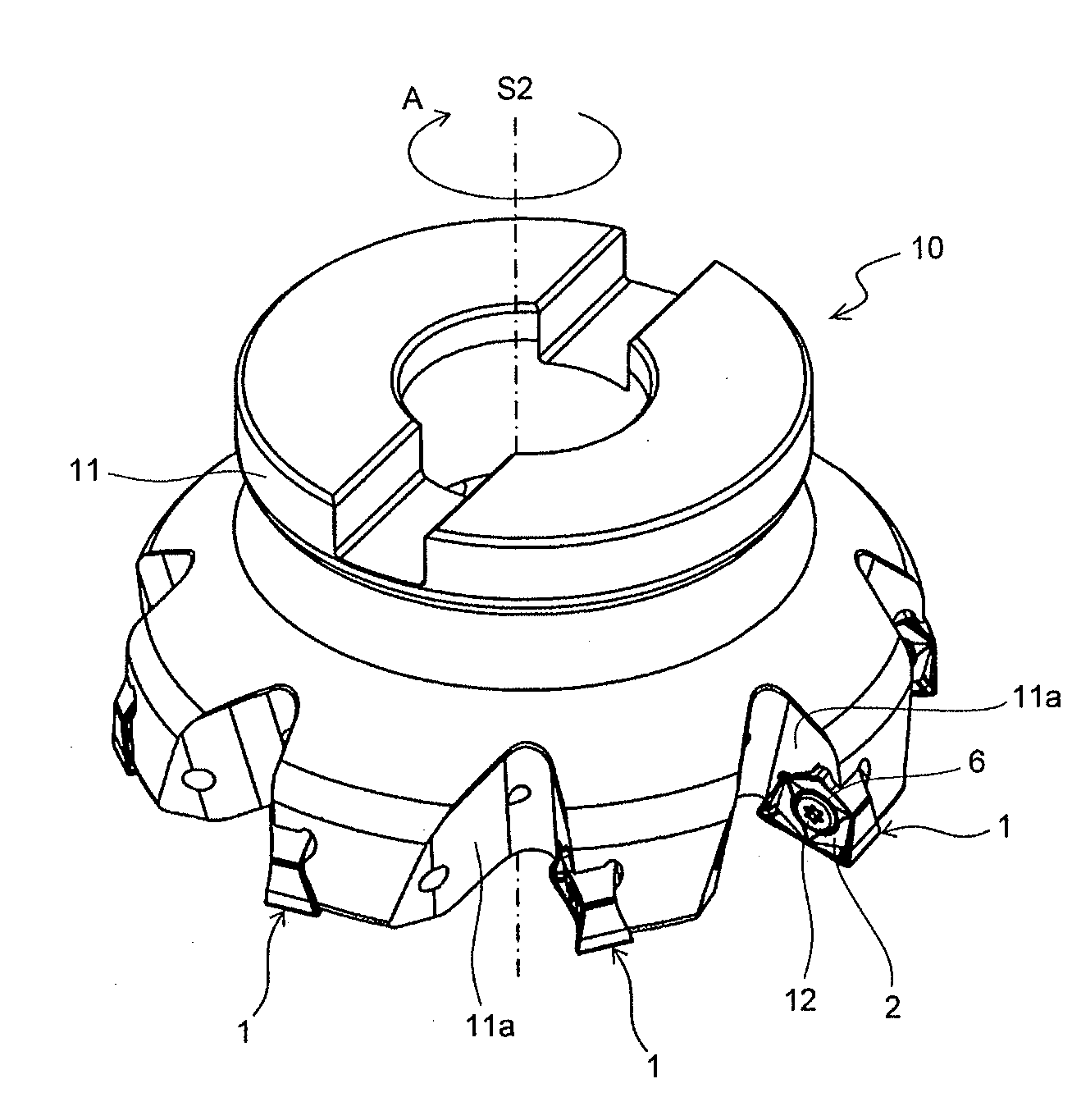
[0081]The step (i) includes rotating the cutting tool 10 around the rotation axis S2 of the holder 11 (cutting tool 10) in the arrowed direction A as shown in FIG. 9(a), and moving the cutting tool 10 in an arrowed direction B so as to bring the cutting tool 10 near the workpiece 100.
[0082]The step (ii) is to bring the upper cutting edge 5 of the cutting tool 10 being rotated into contact with the surface of the workpiece 100 as shown in FIG. 9(b). In the present embodiment, the step (ii) includes the following three substeps.
[0083]The first substep is to allow the cutting tool 10...
second embodiment
[0091]The method of producing a machined product according to the second embodiment is described in details with reference to FIG. 10 by taking so-called plunge milling process as an example.
[0092]The method of producing a machined product according to the present embodiment includes the following steps (i) to (iii). In the following, the order of these steps may be changed suitably unless otherwise stated.
[0093]The step (i) includes rotating the cutting tool 10 around the rotation axis S2 of the holder 11 (cutting tool 10) in an arrowed direction A as shown in FIG. 10(a), and moving the cutting tool 10 in an arrowed direction D so as to bring the cutting tool 10 near the workpiece 100.
[0094]The step (ii) is to bring the upper cutting edge 5 of the cutting tool 10 being rotated into contact with a surface of the workpiece 100 as shown in FIG. 10(b). In the present embodiment, the step (ii) includes the following three substeps.
[0095]The first substep is to allow the cutting tool 10 ...
PUM
| Property | Measurement | Unit |
|---|---|---|
| thick | aaaaa | aaaaa |
| thick | aaaaa | aaaaa |
| angles | aaaaa | aaaaa |
Abstract
Description
Claims
Application Information