
Anisotropic processing of laser speckle images

a laser speckle and anisotropic processing technology, applied in the field of medical imaging, can solve the problems of confounded accurate representation of blood velocity, interference pattern of speckles, and coherent illumination on living tissu

Active Publication Date: 2014-10-23
THE JOHN HOPKINS UNIV SCHOOL OF MEDICINE
View PDF2 Cites 17 Cited by
  • Summary
  • Abstract
  • Description
  • Claims
  • Application Information

AI Technical Summary

Benefits of technology

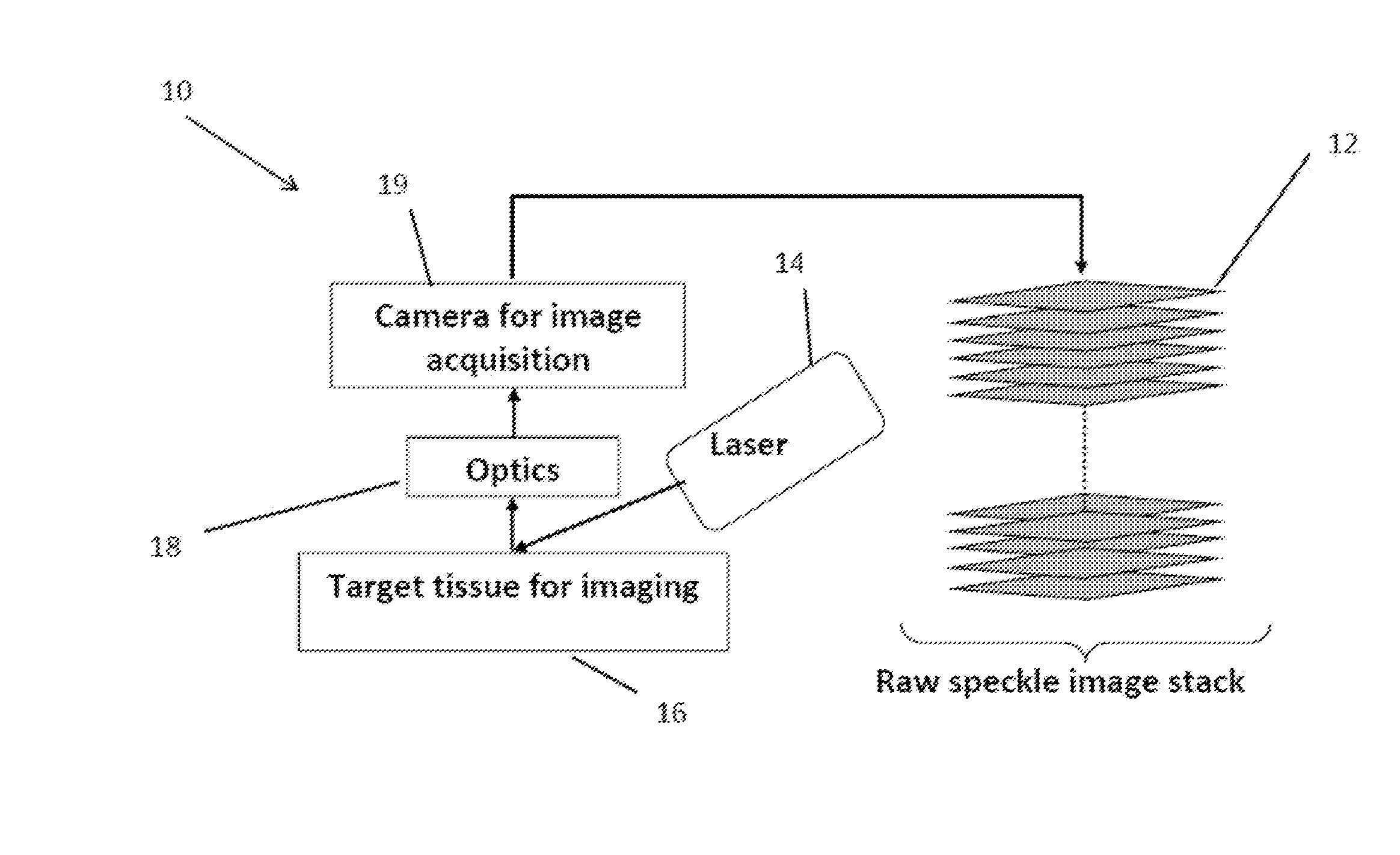
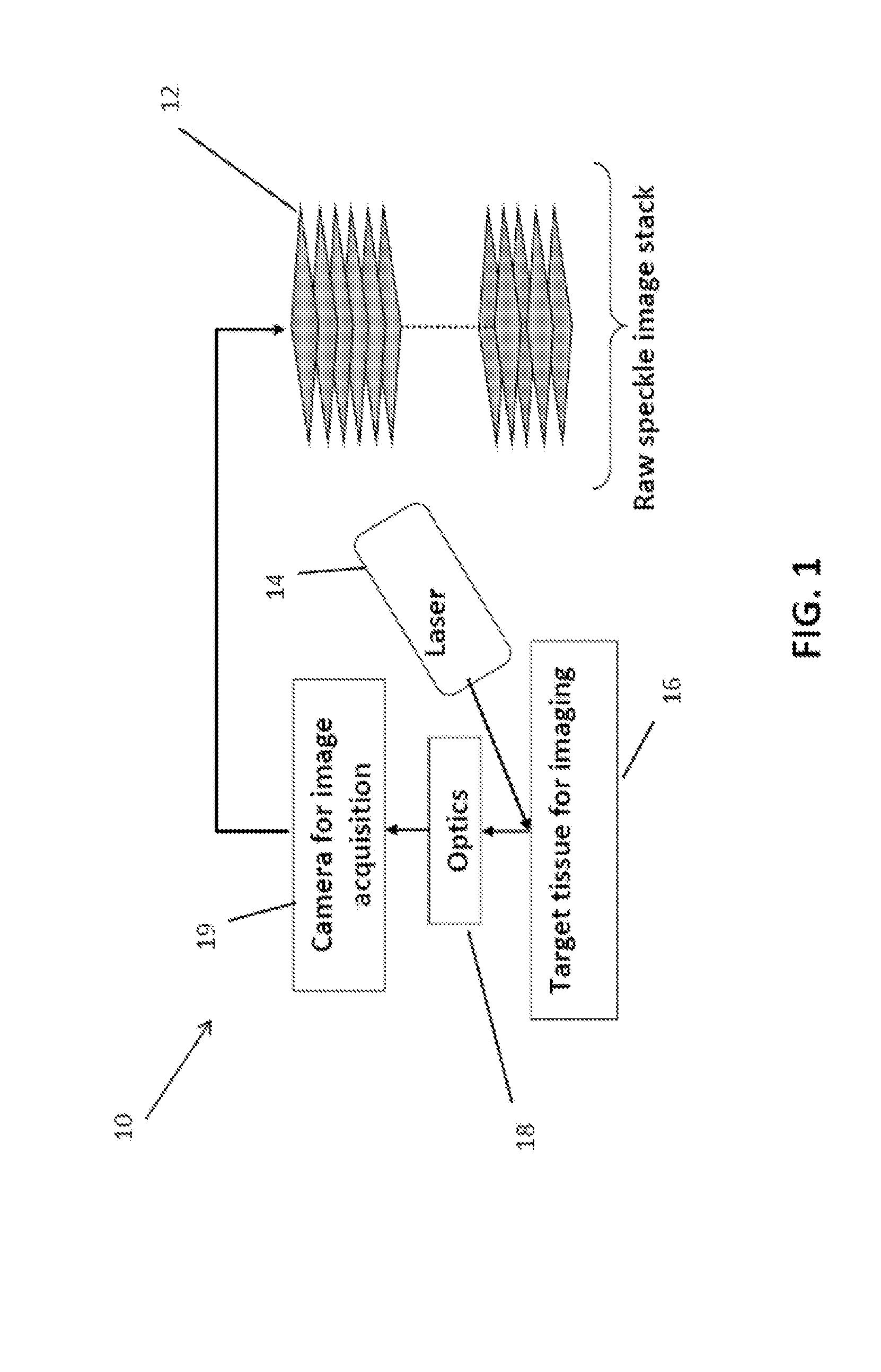
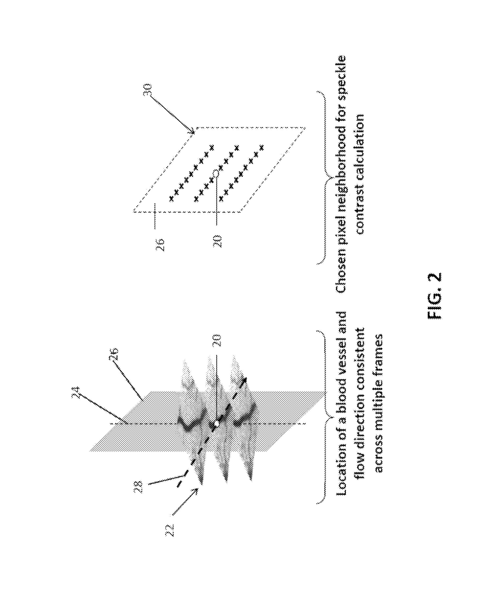
The present invention relates to a system for imaging blood flow and vascular morphology in tissues. The system uses an anisotropic local neighborhood to align pixels in the image in a smooth curve or piece-wise linear fashion. The imaging system can be used in various applications such as imaging blood flow in tissue, vascular morphology, changes in blood flow, tissue perfusion, and monitoring disease states or therapy outcomes. The system has the ability for display, storage, and transmission of the raw laser speckle images and generated anisotropic laser speckle contrast images. Users can also control imaging parameters through an interface device.

Problems solved by technology

Incidence of coherent illumination on living tissue gives rise to interference patterns called speckles.
Because traditional speckle contrast processing schemes use pixel neighborhoods that are isotropic in the spatial domain, often a square of pixels, accurate representation of blood velocity is confounded.

Method used


Image

  • Anisotropic processing of laser speckle images
  • Anisotropic processing of laser speckle images
  • Anisotropic processing of laser speckle images

Examples


example

[0046]The following discussion is included merely by way of example. It is provided to illustrate the methods and system set forth and discussed above. This example, therefore, is not meant to be considered limiting to the scope and application of the methods and systems described above. Further, any application know to or conceivable by one of skill in the art could also be used with the above described methods and systems.

[0047]As an exemplary embodiment, the anisotropic laser speckle contrast imaging (aLSCI) invention was implemented and characterized in a rat brain model of microvascular imaging. This embodiment involved the use of 632 nm (red) He Ne laser illumination and a 16 bit cooled CCD camera for image acquisition, as shown in FIG. 6. The optical assembly provided a magnification of 1:1 and numerical aperture (f-number) of 4.0 thus producing speckles ˜12.45 micrometers in diameter, which is approximately twice our pixel size of 6.7 micrometers. A stack of 75 raw speckle i...


PUM


Abstract

An embodiment in accordance with the present invention provides a system and method for imaging living tissue and processing laser speckle data anisotropically to calculate laser speckle contrast preferentially along the direction of blood flow. In the present invention, raw laser speckle images are obtained and processed resulting in the anisotropic laser speckle images. The system and method involve the determination of the direction of blood flow for every pixel within the region of interest (primary pixel) and subsequent extraction of a set of secondary pixels in the spatio-temporal neighborhood of the primary pixel that is anisotropic in the direction of blood flow. Speckle contrast is then calculated for every primary pixel as the ratio of standard deviation and mean of all secondary pixels in this anisotropic neighborhood and collectively plotted using a suitable color mapping scheme to obtain an anisotropic laser speckle contrast image of the region of interest.

Description

CROSS REFERENCE TO RELATED APPLICATIONS[0001]This application claims the benefit of U.S. Provisional Patent Application No. 61 / 539,042, filed Sep. 26, 2011, which is incorporated by reference herein, in its entirety.GOVERNMENT SUPPORT[0002]This invention was made with government support under grants UL1RR025005 and R21EB012829-01A1 awarded by the National Institutes of Health. The government has certain rights in the invention.FIELD OF THE INVENTION[0003]The present invention relates generally to medical imaging. More particularly, the present invention relates to a method of laser speckle imaging.BACKGROUND OF THE INVENTION[0004]Laser speckle contrast imaging (LSCI) is a non-scanning, wide-field technique useful in visualizing blood vessels and blood flow without the introduction of any exogenous contrast agents. It has been widely used in neuroscience research. Incidence of coherent illumination on living tissue gives rise to interference patterns called speckles. When this speckl...

Claims


Application Information

Patent Timeline
Patent Type & Authority Applications(United States)
IPC IPC(8): A61B5/026
CPCA61B5/0261
Inventor REGE, ABHISHEKSENARATHNA, JANAKATHAKOR, NITISH V.
Owner THE JOHN HOPKINS UNIV SCHOOL OF MEDICINE
Learn More