Container house having structural stability

a container house and structural technology, applied in the field of container houses, can solve the problems of limited container house size and weak prefabricated container houses, and achieve the effects of convenient installation, convenient reception and convenient fixing to the ground

Inactive Publication Date: 2014-10-30
EOM HO SEOB
View PDF16 Cites 17 Cited by
  • Summary
  • Abstract
  • Description
  • Claims
  • Application Information

AI Technical Summary

Benefits of technology

[0025]The present invention has an advantage that the main body can be conveniently and easily fixed to the ground by using piles that firmly fix the main body of the container house to the ground and pass through corner portions of the main body to stick in the ground. That is, as a single-storied or multiple-storied main body is firmly fixed to the ground by a plurality of piles that firmly stick in the ground, the container house can be maintained even in natural disasters such as hurricanes, earthquakes, and the like. Therefore, it is possible that persons comfortably live in poor environments such as a desert, grassland, and the like.
[0026]Further, the present invention has an advantage that at least any one of piles used for fixing a main body to the ground is extended to the top to install the extended pile for installing a solar panel of a self-generation solar generating facility and/or a blade of a wind power generating device on the top. That

Problems solved by technology

Therefore, the size of the container house is limited.
However, since most prefabricated container houses are made of ABS, FRP, and the like which are lightweight and high-strength plastic series materials, it is favorable to transport and install the prefabricated container house, but the prefabricated container houses are weak to a strong wind.
However, the technology needs to perform a complicated process in which the iron structure 110 is separately provided to fix the prefabricated c

Method used


Image

  • Container house having structural stability
  • Container house having structural stability
  • Container house having structural stability

Examples


first embodiment

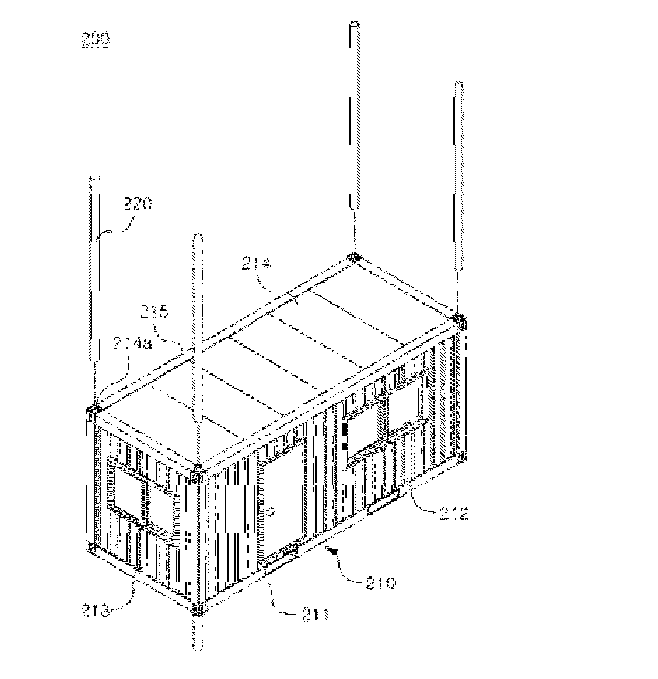
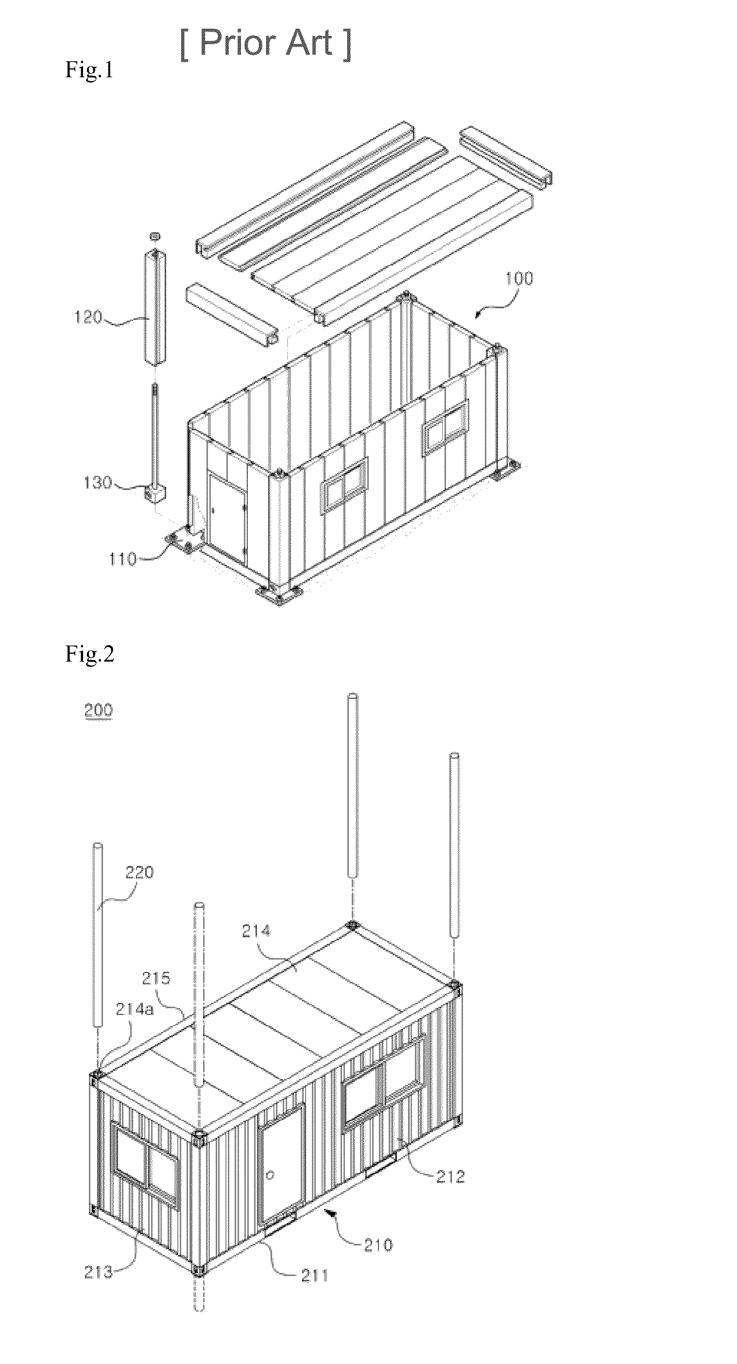
[0029]FIG. 2 is an exploded perspective view illustrating a configuration relationship of a container house having structural stability of a single story according to the present invention.

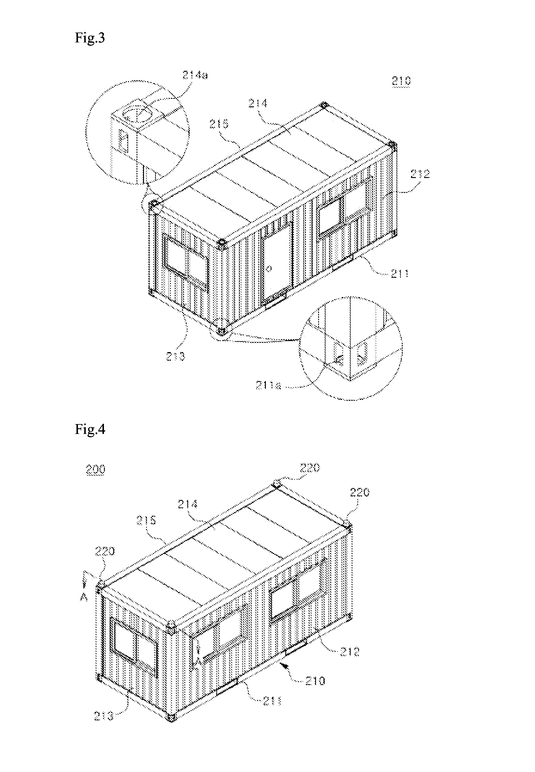
[0030]FIG. 3 is a perspective view and a partially enlarged diagram illustrating the configuration relationship of the container house illustrated in FIG. 2.

[0031]FIG. 4 is an installation perspective view of a state in which the container house illustrated in FIG. 2 is installed on the ground.

[0032]FIG. 5 is a cross-sectional view of the container house illustrated in FIG. 4 taken along line A-A.

second embodiment

[0033]FIG. 6 is a perspective view illustrating a configuration relationship of a container house having structural stability of multiple stories according to the present invention.

[0034]FIG. 7 is a cross-sectional view of the container house illustrated in FIG. 6 taken along line B-B.

third embodiment

[0035]FIG. 8 is a perspective view illustrating a configuration relationship of a container house having structural stability of multiple stories according to the present invention.

[0036]FIG. 9 is a cross-sectional view of the container house illustrated in FIG. 8 taken along line C-C.


PUM


Abstract

The present invention relates to a container house 200 having structural stability and including: a main body 210 having an inner space and a passage connecting the inside to the outside; and a plurality of piles 220 firmly fixing the main body to the ground, wherein the plurality of piles vertically pass through the main body and stick in the ground. The present invention has the advantage in which the main body is firmly fixed to the ground, wherein the main body may be conveniently and easily fixed to the ground by using the piles that pass through corner portions of the main body to stick in the ground. That is, since the single or multi-storied main body is fixed to the ground due to the plurality of piles that firmly stick in the ground, the container house may be stably maintained even through natural disasters such as hurricanes, earthquakes, and the like. Thus, it is possible to comfortably live in poor surroundings such as a desert and grassland.

Description

CROSS-REFERENCE TO RELATED APPLICATIONS[0001]This application is a National phase of PCT Patent Application No. PCT / KR2012 / 009368 having International filing date of Nov. 8, 2012, which claims the benefit of priority of Korean Patent Application No. 10-2011-0116824 filed on Nov. 10, 2011. The contents of the above applications are all incorporated by reference as if fully set forth herein in their entirety.TECHNICAL FIELD[0002]The present invention relates to a container house used in residential space, and more particularly, to a container house having structural stability which can conveniently and easily fix the main body to the ground by using piles that firmly fix the main body of the container house to the ground and pass through corner portions of the main body to stick in the ground.[0003]Further, the present invention also relates to a container house having structural stability which extends at least any one of piles used for fixing a main body to the ground to the top to ...

Claims


Application Information

Patent Timeline
IPC IPC(8): E04H9/00E04H1/02
CPCE04H1/02E04H9/00E02D27/12E04B1/0015E04B1/34315E04B1/34815H01Q1/1214E04H1/04E04H1/06E04H1/1205E04H9/028E04H9/14Y02B10/20Y02E10/47F24S25/10Y02E10/50Y02A50/00Y02B10/10E04B1/348
Inventor EOM, HO SEOB
Owner EOM HO SEOB
Why Eureka
Try Eureka