
Optical security device with nanoparticle ink

a technology of optical security and nanoparticles, applied in the field of optical security devices, can solve the problems of difficult replication of the effect of a potential counterfeiter, the use of metallic nanoparticle inks, and the relatively high cost of reflective layers

Inactive Publication Date: 2014-10-30
CCL SECURE PTY LTD
View PDF9 Cites 11 Cited by
  • Summary
  • Abstract
  • Description
  • Claims
  • Application Information

AI Technical Summary

Benefits of technology

The invention is an optical security device that includes a substrate with a metallic nanoparticle ink applied in at least one area on the first surface of the substrate. A high refractive index coating is applied over the metallic nanoparticle ink areas. The metallic nanoparticle ink may be provided in a plurality of parallel lines or circular spots. The size and spacing of the metallic nanoparticle ink is preferably such that it produces an optical density of greater than 0.1. The optical security device may also include a diffractive relief structure on the first or second surface of the substrate. The invention provides an improved optical security device that enhances the security features of diffractive optical elements.

Problems solved by technology

Typically, such a device will produce an optical effect which is difficult for a potential counterfeiter to replicate.
This procedure is effective in providing a reflective layer, however is relatively costly.
The use of metallic nanoparticle inks has previously been problematic, as such inks display weak adhesion to the surfaces to which they are applied.
Consequently, despite the attractive optical properties of these inks, it has proved difficult to effectively use these types of inks in producing optical security devices.

Method used


Image

  • Optical security device with nanoparticle ink
  • Optical security device with nanoparticle ink
  • Optical security device with nanoparticle ink

Examples


Embodiment Construction

Definitions

Security Document

[0048]As used herein, the term security document includes all types of documents and tokens of value and identification documents including, but not limited to the following: items of currency such as banknotes and coins, credit cards, cheques, passports, identity cards, securities and share certificates, driver's licences, deeds of title, travel documents such as airline and train tickets, entrance cards and tickets, birth, death and marriage certificates, and academic transcripts.

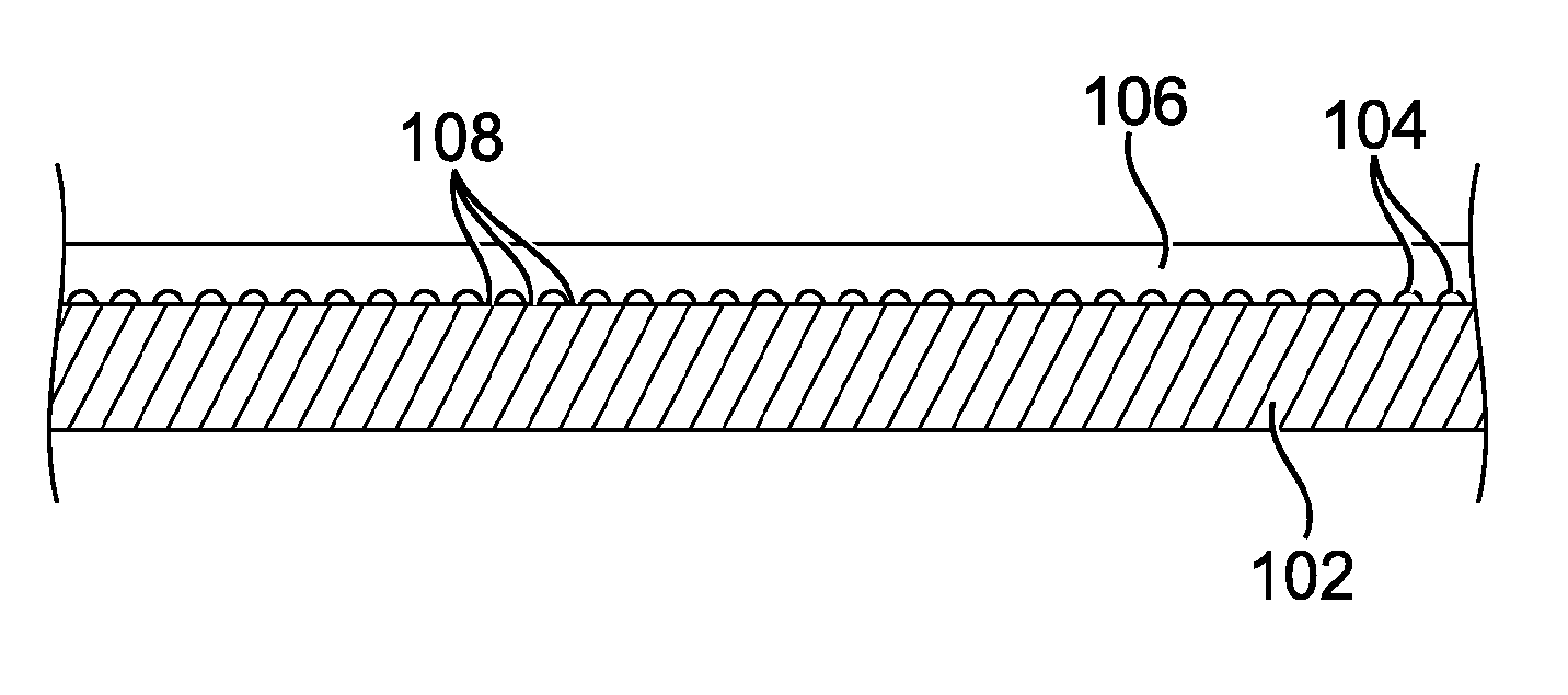
Metallic Nanoparticle Ink

[0049]As used herein, the term metallic nanoparticle ink refers to an ink having metallic particles of an average size of less than one micron.

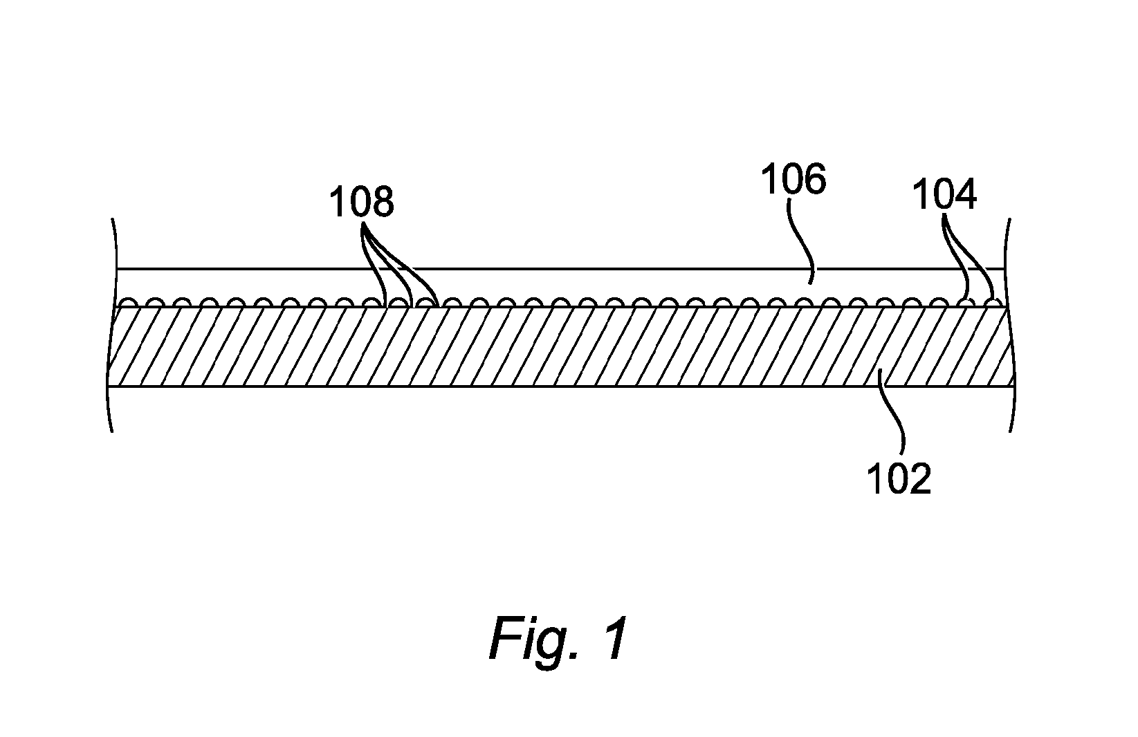
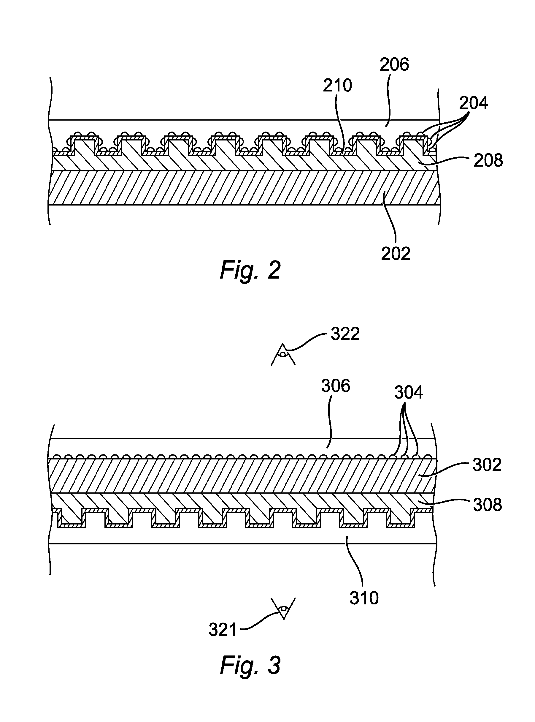
Diffractive Optical Elements (DOEs)

[0050]As used herein, the term diffractive optical element refers to a numerical-type diffractive optical element (DOE). Numerical-type diffractive optical elements (DOEs) rely on the mapping of complex data that reconstruct in the far field (or reconstruction plane) a two-dimen...


PUM

PropertyMeasurementUnit
widthaaaaaaaaaa
diameteraaaaaaaaaa
optical densityaaaaaaaaaa

Abstract

An optical security device, including a substrate (102) having a first surface and a second surface; and a metallic nanoparticle ink (104) provided intermittently in at least one area on the first surface (102) to produce a reflective or partially reflective patch or patches; wherein a high refractive index coating (106) is applied over the area or areas (108) in which the metallic nanoparticle ink is provided, the high refractive index coating (106) adhering to the first surface (102) where the metallic nanoparticle ink is not present, thereby retaining the metallic nanoparticle ink (104) between the first surface (102) and the high refractive index coating (106).

Description

FIELD OF THE INVENTION[0001]This invention relates to optical security devices and methods for their manufacture. More particularly, it relates to optical security devices which utilise a nanoparticle ink in their construction.BACKGROUND TO THE INVENTION[0002]Optical security devices are commonly used in security documents as a means of avoiding unauthorised duplication or forgery of such documents. Typically, such a device will produce an optical effect which is difficult for a potential counterfeiter to replicate.[0003]A wide range of optical security devices are known in the art. Frequently, such devices rely upon the application of a reflective coating or a semitransparent coating with a high refractive index in order to display the optical effect. For example, it is common for an optical security device to be constructed by embossing a diffraction pattern into a polymer layer to form a surface relief pattern, and providing a thin reflective metal layer over the pattern. In this...

Claims


Application Information

Patent Timeline
Patent Type & Authority Applications(United States)
IPC IPC(8): B42D15/00
CPCB42D2031/02B42D15/0013B41M3/14C09D11/037B42D25/351B42D25/328B42D25/378B42D25/373B42D25/324B42D2033/10B42D2033/18B42D2035/20B42D25/29B42D25/405C09D11/00
Inventor POWER, GARY FAIRLESSBATISTATOS, ODISEALOK, PHEIHARDWICK, MICHAEL BRUCE
Owner CCL SECURE PTY LTD
Learn More