
Power conversion device

a power conversion device and power technology, applied in the direction of dc-dc conversion, power conversion systems, electrical apparatus, etc., can solve the problems of reducing the reliability of reverse-blocking insulated gate bipolar transistors, increasing loss, and reducing the conversion efficiency of power conversion devices, so as to reduce the loss resulting from leakage current and suppress leakage current.

Active Publication Date: 2014-10-30
FUJI ELECTRIC CO LTD
View PDF6 Cites 6 Cited by
  • Summary
  • Abstract
  • Description
  • Claims
  • Application Information

AI Technical Summary

Benefits of technology

The invention provides a device that can convert power more efficiently, reducing the loss of power caused by leakage current. This means that the device can better manage the flow of electricity, minimizing the loss of energy when it is applied in reverse.

Problems solved by technology

An increase in the leakage current when the reverse voltage is applied causes an increase in loss.
Further, the increase in loss leads to a decrease in the reliability of the reverse-blocking insulated gate bipolar transistor and a reduction in the conversion efficiency of the power conversion device.

Method used


Image

  • Power conversion device
  • Power conversion device
  • Power conversion device

Examples


Embodiment Construction

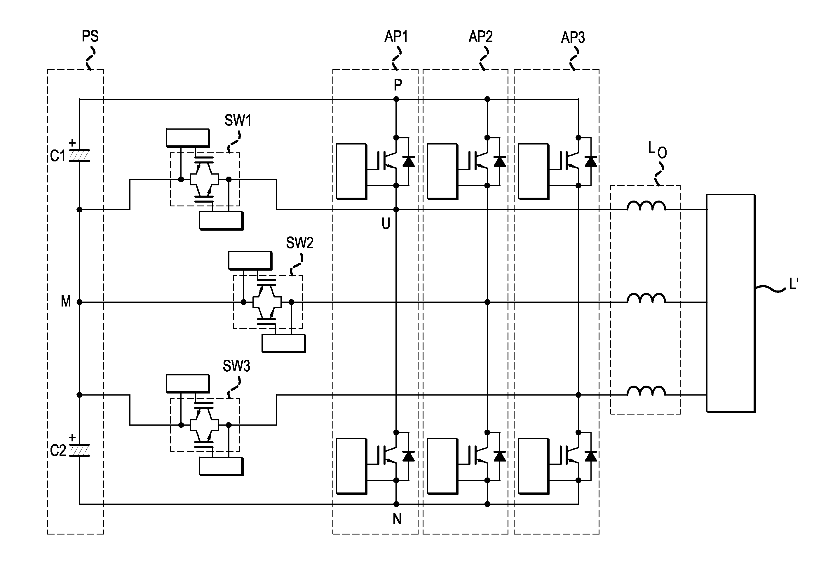
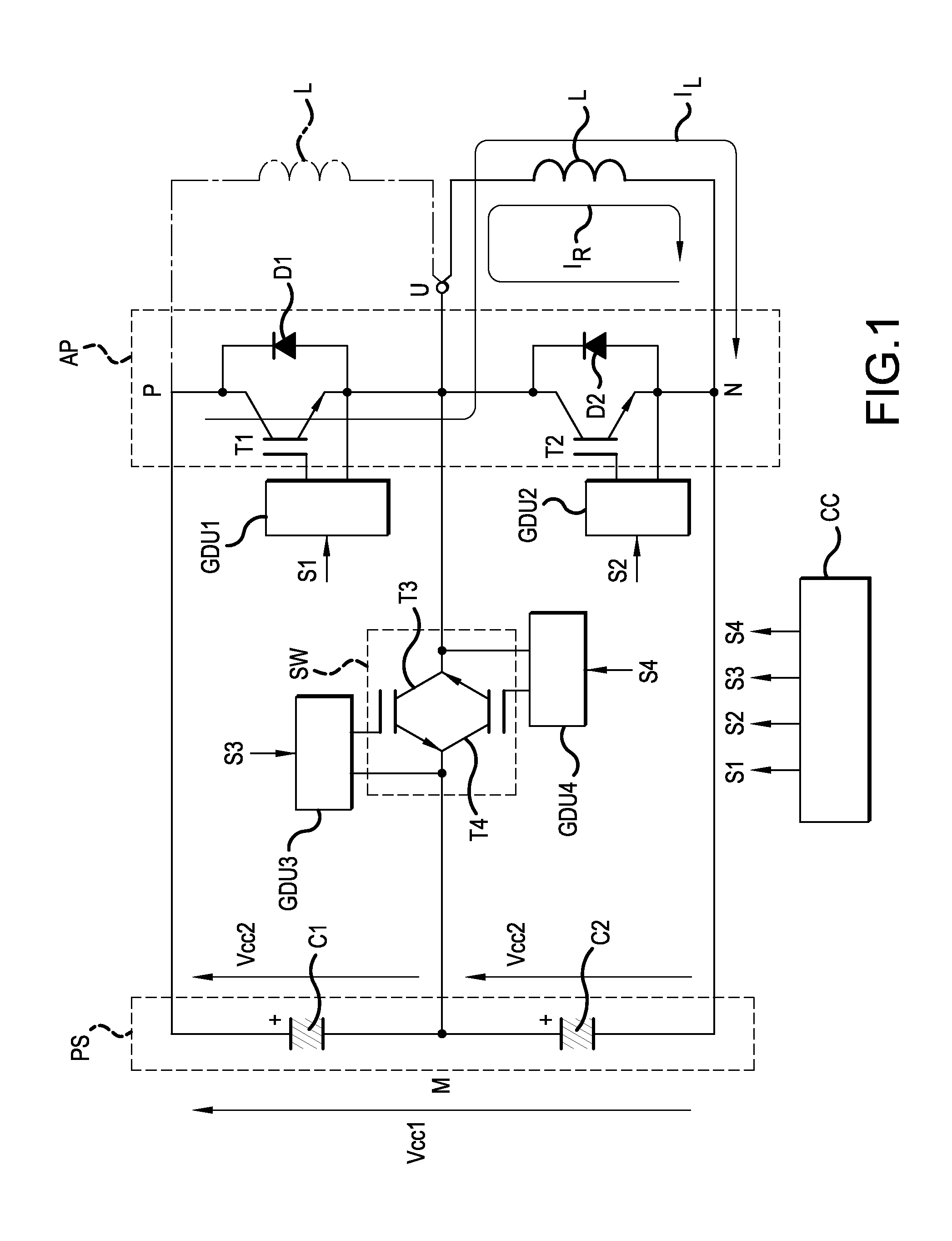
[0031]FIG. 1 is a circuit diagram showing a configuration example of a single-phase three-level power conversion device (inverter) according to an embodiment of the invention. The power conversion device includes a direct current power source PS, an arm pair AP, and a bidirectional switch (alternating current switch) SW.

[0032]The power source PS includes capacitors C1 and C2 connected in series. The terminal voltages of the capacitors C1 and C2 are both Vcc2. Consequently, a voltage Vcc1 between the positive electrode and negative electrode of the power source PS is 2×Vcc2.

[0033]The arm pair AP includes semiconductor switch elements T1 and T2 connected in series and free wheel diodes D1 and D2 connected in parallel to the respective semiconductor switch elements T1 and T2. In this embodiment, an insulated gate bipolar transistor (IGBT) is used as the semiconductor switch elements T1 and T2, but in place of this, it is also possible to use another semiconductor switch element.

[0034]T...


PUM


Abstract

An increase in leakage current when a reverse voltage is applied to reverse-blocking insulated gate bipolar transistors is suppressed, thus reducing a loss resulting from the leakage current. A power conversion device includes a bidirectional switch formed by connecting two reverse-blocking insulated gate bipolar transistors having reverse breakdown voltage characteristics in reverse parallel. A control circuit is configured so as to output command signals for bringing the gates of the reverse-blocking insulated gate bipolar transistors, to which a reverse voltage is applied, into an on state.

Description

CROSS-REFERENCE TO RELATED APPLICATIONS[0001]This application is a continuation of International Application No. PCT / JP2013 / 052318, filed on Feb. 1, 2013, which is based on and claims priority to Japanese Patent Application No. JP 2012-081718, filed on Mar. 30, 2012. The disclosure of the Japanese priority application and the PCT application in their entirety, including the drawings, claims, and the specification thereof, are incorporated herein by reference.BACKGROUND[0002]1. Field of the Invention[0003]Embodiments of the present invention relate to a power conversion device using a bidirectional switch formed by connecting reverse-blocking insulated gate bipolar transistors in reverse parallel.[0004]2. Description of the Background[0005]A bidirectional switch formed by connecting reverse-blocking insulated gate bipolar transistors (RB-IGBTs) in reverse parallel, as it has low loss characteristics, is put to practical use in a power conversion device such as an inverter or a conver...

Claims


Application Information

Patent Timeline
IPC IPC(8): H02M7/483
CPCH02M7/483H02M7/487H02M7/5387H02M3/1555
Inventor CHEN, SHUANGCHING
Owner FUJI ELECTRIC CO LTD
Learn More