Compact non-electric medicament infuser

a non-electric, infuser technology, applied in the direction of filtering accessories, valves, intravenous devices, etc., can solve the problems of pump failure, inability to easily change the force, incomplete or inaccurate medication delivery, etc., to achieve the effect of convenient attachment to the patien

Active Publication Date: 2014-10-30
DUNCAN DAVID R
View PDF7 Cites 35 Cited by
  • Summary
  • Abstract
  • Description
  • Claims
  • Application Information

AI Technical Summary

Benefits of technology

[0027]Another object of the present invention is to provide a medicament infuser that may be easily attached to the patient.

Problems solved by technology

Gravity fed infusion systems have limitations in that the amount of force cannot be readily changed, other than through the imprecise method of increasing the elevation of the supply reservoir.
These electronic infusion pumps have the benefit of being able to utilize electrically driven displays and commonly available buttons and dials for thorough control of infusion rates and volumes, but also have significant deficiencies including a reliance on their internal mechanisms and a continuous source of electricity.
If the power supplied from the AC plug or the DC battery is discontinued, full or partial failure of the pump may occur, causing incomplete or inaccurate medication delivery.
The pump may also fail with respect to its electronic or mechanical parts within.
These sorts of failures often lead to medication errors causing significant patient morbidity and mortality.
These complex, expensive pumps increase the cost of delivering medical care, are cumbersome to use, require troubleshooting and frequent service.
In addition, some magnetic or electric medical equipment can be interfered with by other equipment containing metal or generating electric signals, presenting a need for non-electric and / or nonmetallic infusion devices.
The prior art patents to Yamada (U.S. Pat. No. 5,807,337) and Mitchell (U.S. Pat. No. 5,024,664) demonstrate vacuum powered infusion devices with several limitations and have never attained significant clinical use.
These devices connect the drive section to the syringe / load chamber section, which does not allow for independent operation of the two sections.
This deficiency does not allow one to use the syringe section to self load by aspiration, nor does it allow one to readily discontinue and / or restart infusion by disengaging or reengaging the drive section from the medicament containing (syringe-like) section.
These additional steps, such as loading one syringe first to inject medicament into another, greatly increases the chance of medication error.
Another limitation with these infusers is the lack of a guide or stabilizer to assure linear translation of the plungers during infusion.
If the Yamada or Mitchell device plungers were significantly extended as with a significantly “full” device, there would be degree of rotation, flex and increased “play” in the apparatus which would allow increased friction and unreliable or nonlinear infusion rates.
Another limitation of the Yamada and Mitchell devices is the difficulty faced with a loss of vacuum.
Manipulation of a rubber plug is cumbersome and time consuming.
Another limitation of these devices is the lack of a handle to independently operate the drive section.
This deficiency is severely limiting and clearly demonstrates these devices are meant to be loaded with medicament only through the use of the second syringe as mentioned above, thereby extending the load chamber and drive section together and not allowing for independent operation of either section.
This deficiency yields an inability to rapidly discontinue, start, or restart medicament infusion and maintains the load chamber in an always pressurized state making any attempt at placing medicament into the device cumbersome.
The device rigidly connects the drive section to the syringe / load chamber section, which does not allow for independent operation of the two sections.
These deficiencies do not allow one to use the syringe section to self load by aspiration, nor does it allow one to readily discontinue and / or restart infusion by disengaging or reengaging the drive section from the medicament containing section.

Method used


Image

  • Compact non-electric medicament infuser
  • Compact non-electric medicament infuser
  • Compact non-electric medicament infuser

Examples


Embodiment Construction

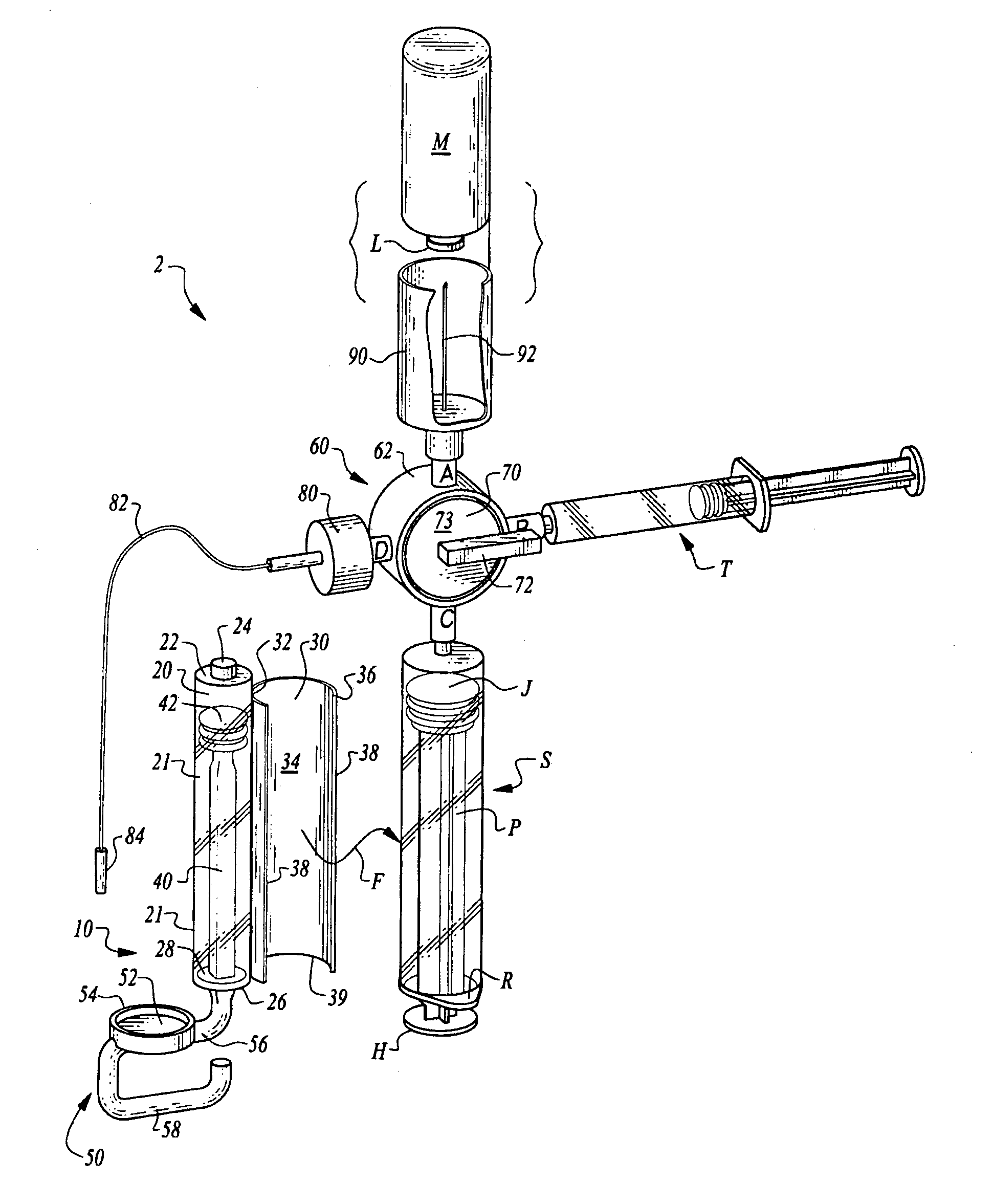
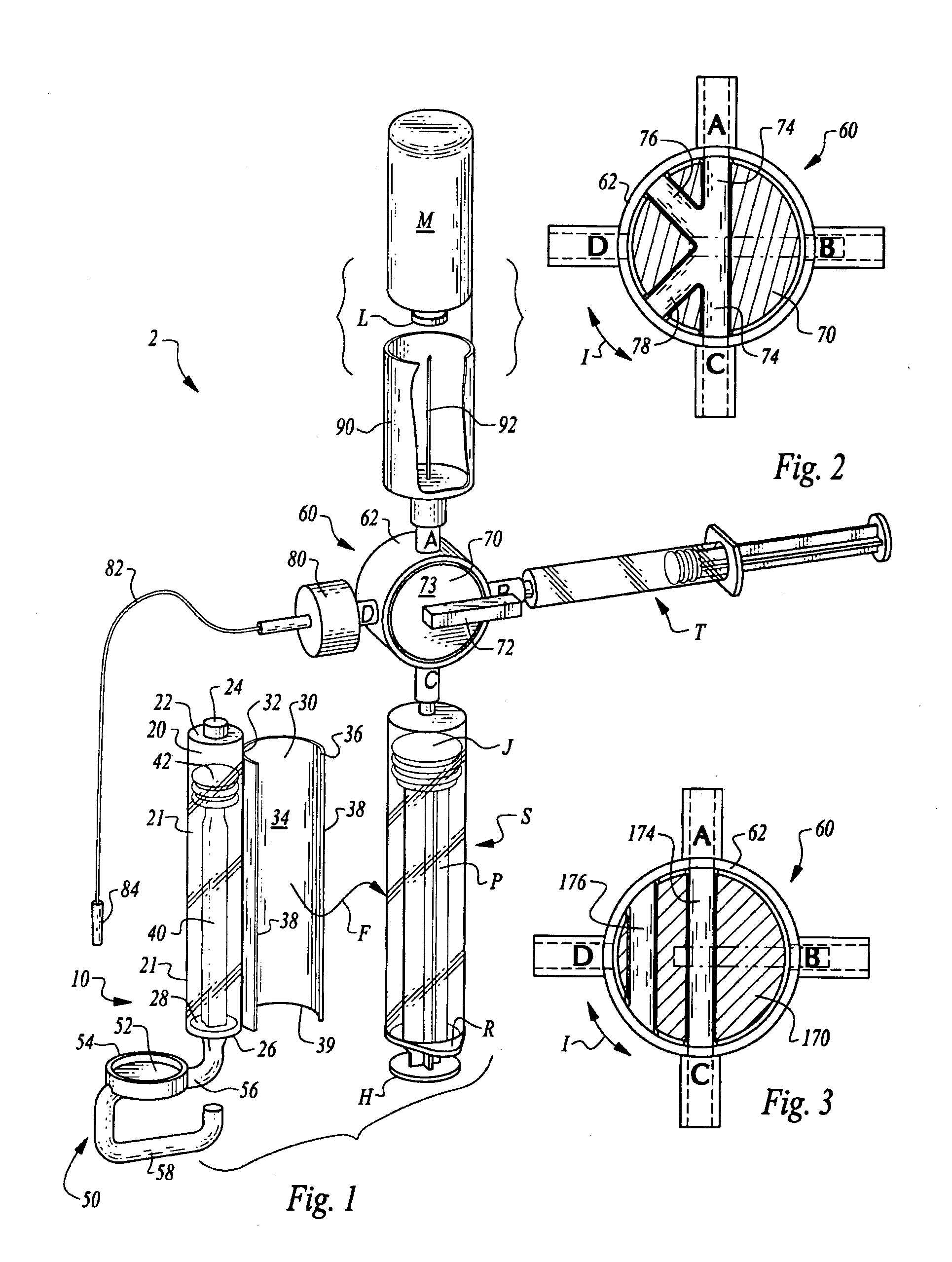
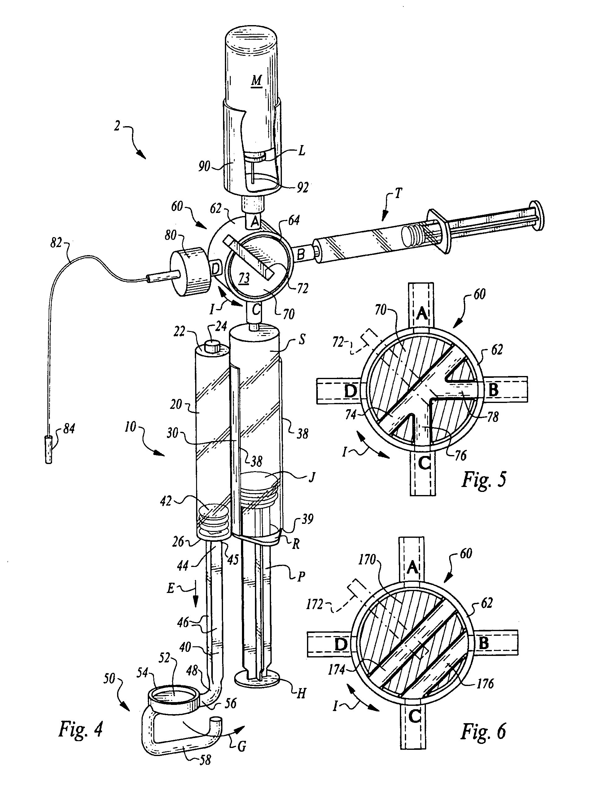
[0055]Referring to the drawings, wherein like reference numerals represent like parts throughout the various drawing figures, reference numeral 10 is directed to an infusion device for use with a syringe S, such as within an overall infusion assembly 2 for delivery of medicament over time from the syringe S into a patient or animal. The infusion device 10 utilizes a vacuum or another resistance based force to energize and “activate” the arm 40 and driver 50. The arm 40 and driver 50 together are known as the force applicator and when activated, may act upon a plunger P of the syringe S so that a piston J within the syringe S moves to drive the medicament out of the syringe S and to the patient.

[0056]In essence, and with particular reference to FIG. 1, basic details of this invention are described, according to a preferred embodiment. The infusion assembly 2 in this preferred embodiment includes the infusion device 10 removably coupleable (along arrow F) to the syringe S. The syringe...


PUM


Abstract

An assembly is provided which includes an infusion device coupled to a standard medication syringe. The medication syringe may be coupled to a stopcock valve having multiple ports and to which syringes, vial adapters, infusion tubing, and multiple other items may be coupled. The infusion device includes a source of power based on a resistance force such as vacuum, spring or gas power. The infusion device converts the resistance based force to usable work in the form of a force applicator. The force applicator includes a driver section on one section of a reciprocating arm and an attachment to the power source on another section of the arm. The driver is pulled outward (excursion) to increase the size of the chamber, creating a force that tends to return the driver back inward, causing incursion. The driver can be attached removably to the syringe plunger to induce the infusion process.

Description

CROSS-REFERENCE TO RELATED APPLICATIONS[0001]This application claims priority from International Patent Application No. PCT / US2012 / 000550 filed on Nov. 8, 2012.FIELD OF THE INVENTION[0002]The following invention relates to infusion equipment for delivering medicament (medication or other medical preparations) into the bloodstream or other locations within the body of a patient or animal. More particularly, this invention relates to infusion devices which work with a standard medical syringe to deliver medicament from the syringe over a desired period of time and in a manner which does not require electronics or coupling to an external power source for proper function.BACKGROUND OF THE INVENTION[0003]Many medicaments require infusion into a patient or animal over an extended period of time, rather than in a single immediate dose. Infusion systems are known in the art to allow such medicaments to be so infused in a controlled fashion over a period of time. Such infusion systems genera...

Claims


Application Information

Patent Timeline
Patent Type & Authority Applications(United States)
IPC IPC(8): A61M5/145A61M5/165A61M5/315A61M39/22
CPCA61M5/145A61M5/315A61M5/165A61M39/22A61M5/14526A61M5/1454A61M5/19A61M5/20A61M5/2053
Inventor DUNCAN, DAVID R.
Owner DUNCAN DAVID R
Why Eureka
Try Eureka