
Methods and Apparatus for Detecting and Localizing Partial Conductor Failures of Implantable Device Leads

Active Publication Date: 2014-10-30
LAMBDA NU TECH
View PDF2 Cites 20 Cited by
  • Summary
  • Abstract
  • Description
  • Claims
  • Application Information

AI Technical Summary

Benefits of technology

The disclosed method and apparatus can diagnose conductor anomalies in an implantable lead used with an implantable medical device. It does not rely on the behavior of the conductor-tissue interface or other body tissues, but rather measures the impedance of the lead's conductors and electrodes. The small circuit element at the end of the lead helps to remove the conductor-tissue interface from the measurement. This results in more accurate diagnostics for conductor anomalies in implantable medical devices.

Problems solved by technology

The long-term reliability and safety of implantable cardiac leads is a significant issue.
Anomalies of conductors in implantable medical devices constitute a major cause of morbidity.
The most common presentation of pace-sense failures is oversensing of rapid, nonphysiological signals.
Prior to the implementation of diagnostics that incorporated oversensing, pace-sense fractures presented most commonly as inappropriate shocks, despite daily, automated measurements of pacing impedance.
Functional failure of a pace-sense conductor or oversensing also results in inhibition of bradycardia pacing, cardiac resynchronization, or antitachycardia pacing.
Lead insulation failure or fractures may also present with loss of capture.
High-voltage conductor failures present with potentially fatal failed defibrillation or cardioversion.
A false positive clinical diagnosis of insulation failure results in unnecessary lead replacement, with corresponding expense and surgical risk.
In fact, with presently-used methods, abnormal increases in impedance occur before diagnostic oversensing—and usually shocks—in only 28% of confirmed Fidelis fractures.
Further, resistance measurements have limited specificity.
A single, out-of-range value may be an artifact, and marked, persistent increases can occur at the electrode-myocardial interface in normally functioning leads, thus resulting in over diagnosis of lead failures.
However, these types of “impedance monitoring,” which return values close to direct current resistance, identify lead anomalies before inappropriate shocks in only about a third of ICD patients who have conductor fractures.
Repetitive oversensing of nonphysiologically-short intervals may indicate lead conductor fracture even if lead resistance is normal.
Thus, it will not detect a lead anomaly if it does not generate “noise signals” or if it generates only low-amplitude noise signals, or signals that do not occur at a fast enough rate.
However, it requires sufficient oversensing to result in inappropriate detection of ventricular fibrillation clinically.
Thus, it does not provide early diagnosis of conductor anomalies.
Withholding shocks for ventricular fibrillation detected on the near-field electrogram has an inherent risk of withholding life-saving therapy, however small, and is, thus, not the preferred approach to diagnosis conductor fracture.
Like the Lead-Integrity Alert method, it is not applicable to intraoperative diagnosis or to pacemakers and neurostimulators.
Comparable limitations apply to measuring impedance of the high-voltage lead components.
Thus, impedance measurements are correspondingly insensitive to significant changes in cable or coil impedance.
In addition to limited sensitivity, present methods for diagnosing lead conductor anomalies have limited specificity resulting in false positive diagnostics.
Evaluation of false positive diagnostics adds cost and work to medical care and may contribute to patient anxiety.
If a false-positive diagnostic is not diagnosed correctly, patients may be subject to unnecessary surgical lead replacement with its corresponding risks.
Existing technology for diagnosis of conductor anomalies in an implantable medical device is believed to have significant limitations and shortcomings.

Method used


Image

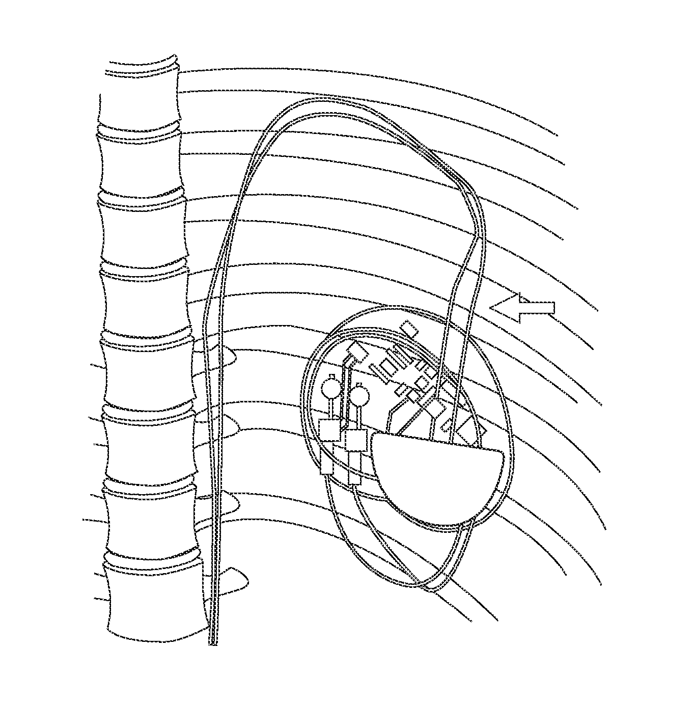
  • Methods and Apparatus for Detecting and Localizing Partial Conductor Failures of Implantable Device Leads
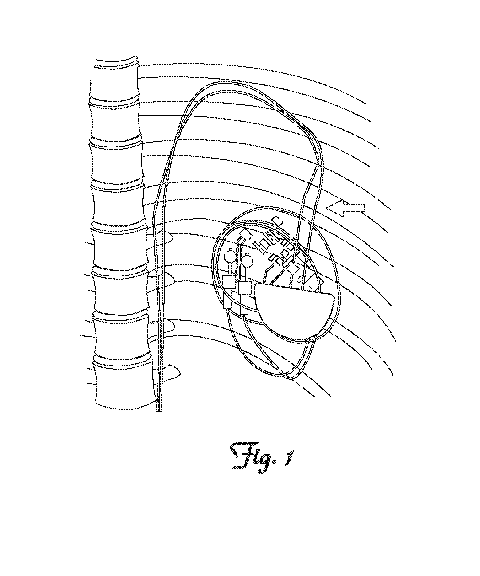
  • Methods and Apparatus for Detecting and Localizing Partial Conductor Failures of Implantable Device Leads
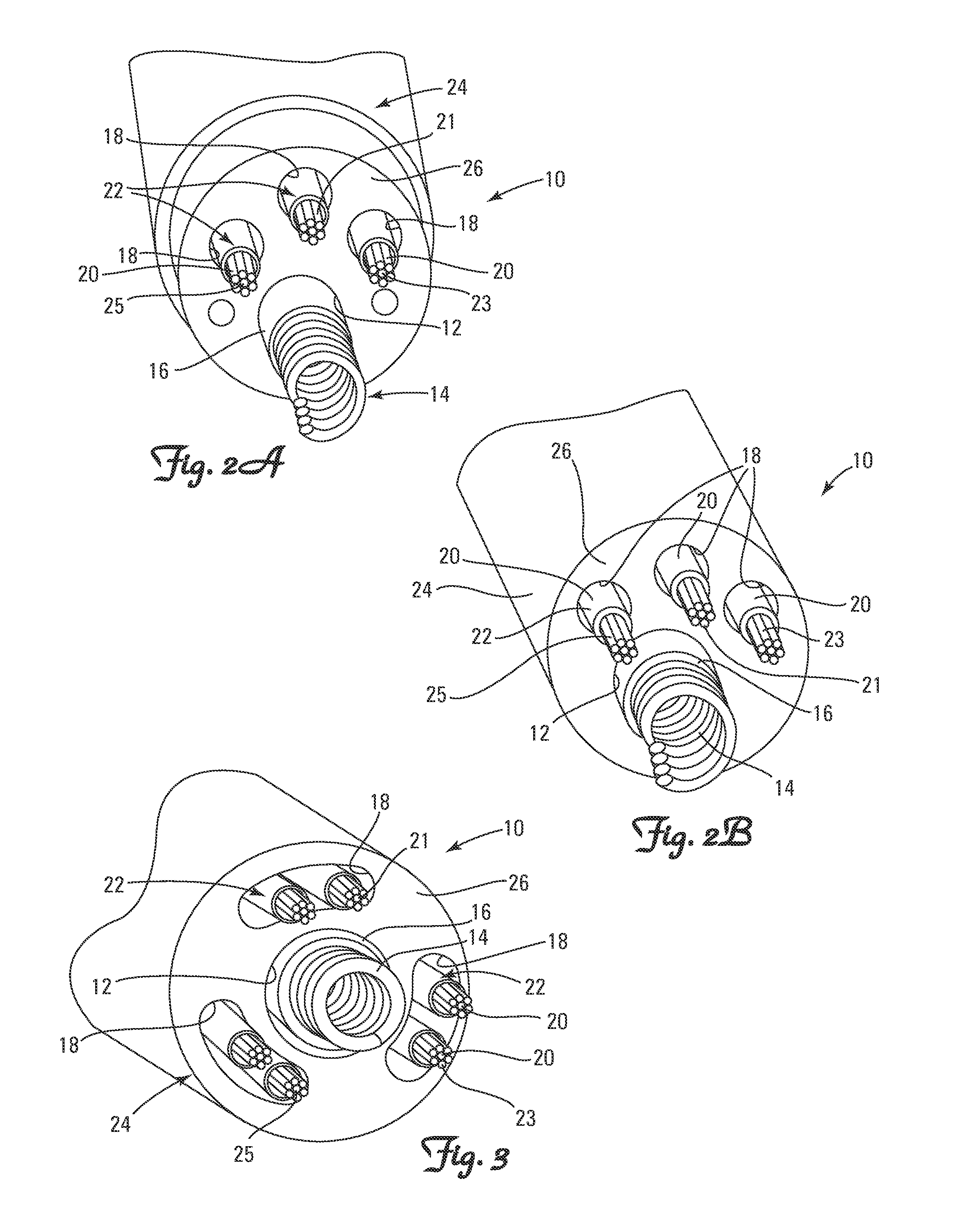
  • Methods and Apparatus for Detecting and Localizing Partial Conductor Failures of Implantable Device Leads

Examples


embodiment 80

[0051]In another embodiment, a capacitor embodiment 80 could be used for the RV coil conductor impedance measurement. The capacitance ranges discussed earlier are acceptable and would not conduct sufficient energy or current to cause damage. While there would be a short high-current spike, its duration would be too short to cause electroporation stunning

[0052]In general, the input impedance Zin of a transmission line, with an excitation wavelength of, is given by:

Zin=Z0ZL+jZ0tan(βl)Z0+jZLtan(βl)[0053]where =2π / ZL is the load impedance, and Z0 is the characteristic impedance of the transmission line.

[0054]For the special case where a frequency with a multiple of a half-wavelength (of the lead) is used, the tangent terms become 0 and the equation reduces to:

Zin=ZL

so that the input impedance equals the load impedance.

[0055]Modern ICD leads are complex and hence their impedance spectra are more complex than the ideal simple transmission line.

[0056]The plot of the impedance spectra of a...

embodiment 70

[0058]FIG. 11 depicts an embodiment of an ICD lead 110 using the diode embodiment 70 along with typical MRI protection components 91 to aid in identifying small changes in the lead impedance. Shown is a partial schematic of an ICD lead 110. This embodiment depicts the combination of the impedance-testing diode 72 for both the tip-ring conductor pair and the RV coil-ring conductor pair. Because of the diode 72 configuration, this approach has the disadvantage of conducting some of the negative (2nd) phase current thru the tip. However, the MRI LC tank 91 would be expected to limit this current to a low value.

[0059]FIG. 12 depicts a solid state implementation 120 of an embodiment of the invention. The diode 121 and capacitor 123 scavenge a small amount of charge from the pacing pulses. If testing is required and there have been no pacing pulses, then a few are delivered to charge up the distal capacitor which then powers the digital circuit shown in the block diagram of FIG. 12.

[0060]...


PUM


Abstract

Method and apparatus for diagnosis of conductor anomalies, such as partial conductor failures, in an implantable lead for an implantable medical device are disclosed. In various embodiments, small changes in the lead impedance are identified by the use of a small circuit element that is incorporated as part of the distal end of the implantable lead. In various embodiments, the small circuit element is electrically connected to a lead conductor and / or electrode of the implantable lead. Methods of diagnosing conductor anomalies in accordance with these embodiments generate measured values that depend only on the impedance of the conductors and electrodes of the lead, and not on the behavior of the conductor-tissue interface and other body tissues.

Description

RELATED APPLICATION[0001]The present application claims the benefit of U.S. Provisional Application No. 61 / 817,667 filed Apr. 30, 2013, which is incorporated herein in its entirety by reference.FIELD OF THE INVENTION[0002]The present invention relates, generally, to scientific and medical systems, apparatus, and methods. More particularly, the invention relates to method and apparatus for diagnosis of conductor anomalies, such as partial conductor failures, in an implantable lead for an implantable medical device by identifying small changes in the lead impedance by the use of a small circuit element that is connected near the distal end of the lead.BACKGROUND[0003]The long-term reliability and safety of implantable cardiac leads is a significant issue. Anomalies of conductors in implantable medical devices constitute a major cause of morbidity. Representative examples of such medical devices include, but are not limited to, pacemakers, vagal nerve stimulators, pain stimulators, neu...

Claims


Application Information

Patent Timeline
IPC IPC(8): A61N1/08A61N1/05A61B5/276
CPCA61N1/0563A61N1/08A61B2560/0276A61B5/276A61B5/29
Inventor KROLL, MARK W.SWERDLOW, CHARLES D.
Owner LAMBDA NU TECH
Learn More