Injector control method

a control method and injector technology, applied in the direction of engines, mechanical equipment, machines/engines, etc., can solve the problems of failure to inject urea water, temporary malfunction of failed injection, and inability to mount a vehicle, so as to facilitate the displacement of urea water with the air, excellent effects, and the effect of reducing the performance of the vehicl

Active Publication Date: 2014-11-06
HINO MOTORS LTD
View PDF5 Cites 14 Cited by
  • Summary
  • Abstract
  • Description
  • Claims
  • Application Information

AI Technical Summary

Benefits of technology

[0021]According to the injector control method of the invention mentioned in the above, various excellent effects can be obtained. For example, the operation of temporarily sucking back the urea water in the passage is interposed before the pump is stopped, and the pump is restarted after lapse of a predetermined time, so that the interface between the urea water and the air in the passage is greatly shaken and displacement of the urea water with the air can be facilitated. As a result, the air flows up in the passage and in replacement thereof the urea water flows down in the passage to the injector to dissolve the urea crystals, so that the temporary malfunction of the injector due to the adhesion of the urea crystals can be promptly resolved and a frequency at which abnormality of the injector is diagnosed by self-diagnosis performance of a vehicle can be substantially reduced.

Problems solved by technology

There is, however, a problem that the spaced-apart arrangement of the particulate filter and the selective reduction catalyst with a sufficient distance in between would significantly impair a mountability on a vehicle.
In the urea water adding injector 8 provided in the exhaust emission control device as mentioned in the above, urea crystals may precipitate in a nozzle of the injector under specific conditions such as sudden stop of the engine having been in operation with high exhaust temperature, which may bring about temporary malfunction of failed urea-water injection due to adhesion of the precipitating urea crystals.

Method used


Image

  • Injector control method
  • Injector control method
  • Injector control method

Examples


Embodiment Construction

[0027]Next, an embodiment of the invention will be described in conjunction with the drawings.

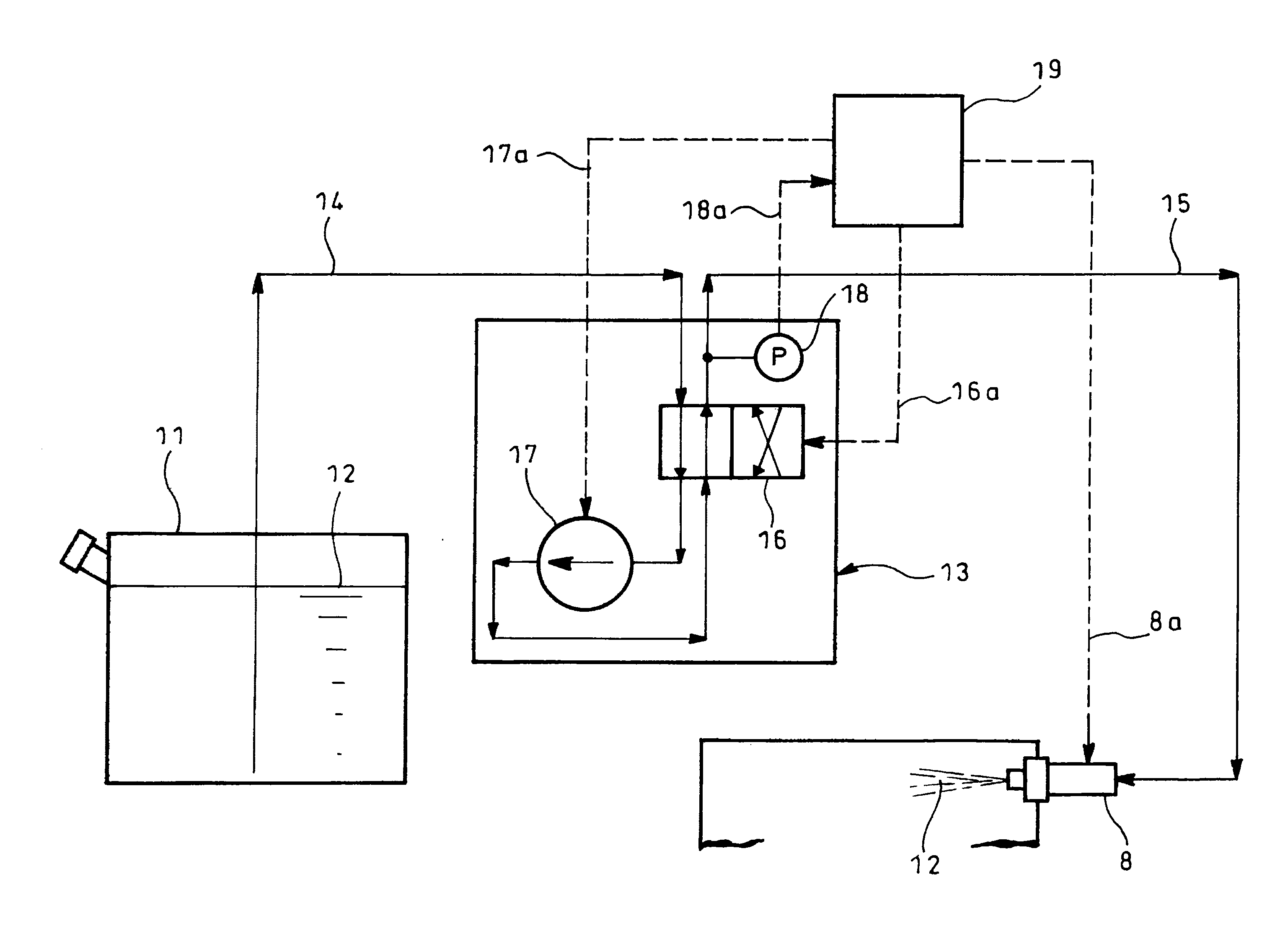
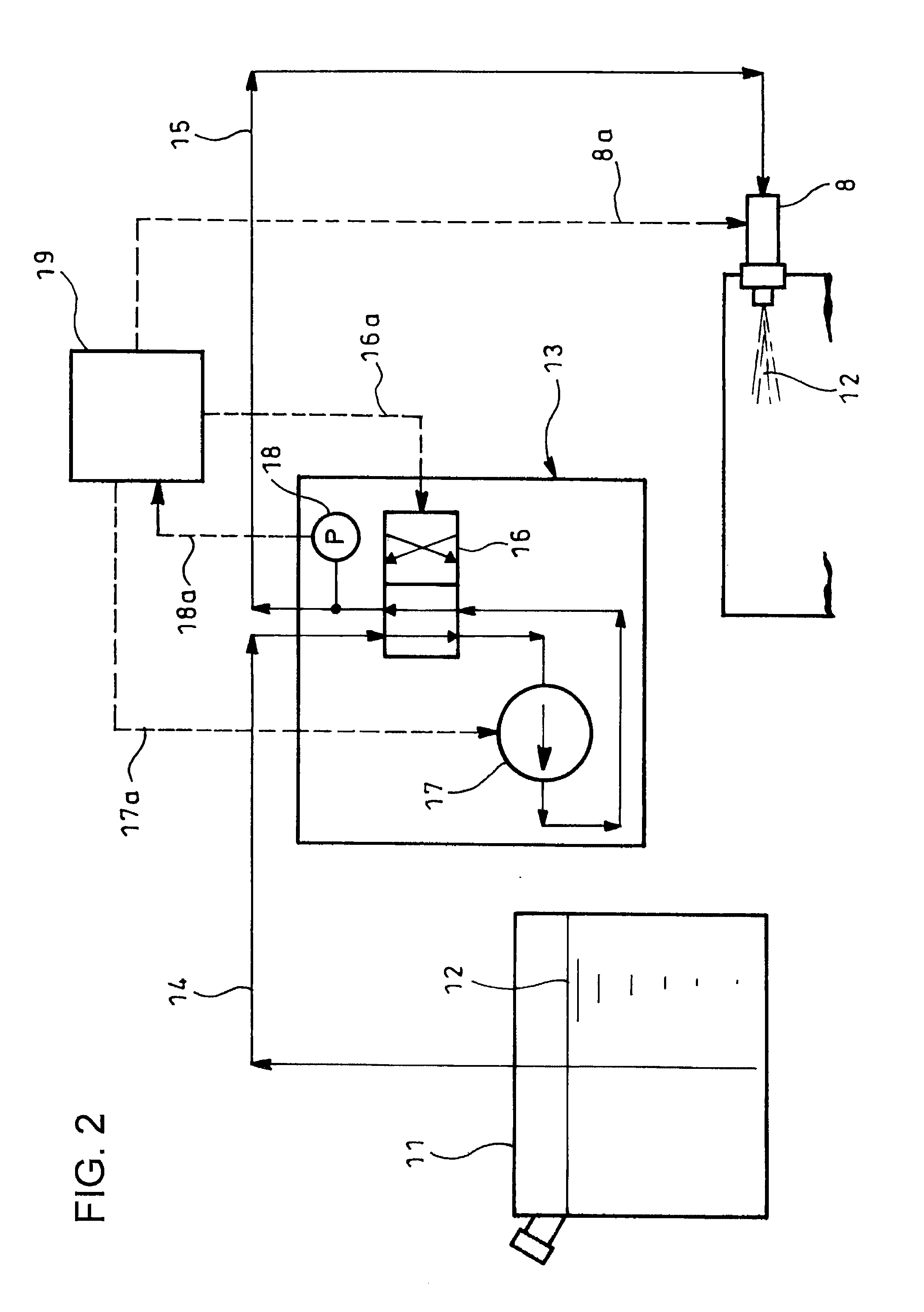
[0028]FIGS. 2-5 show the embodiment of the invention. In FIG. 2, reference numeral 11 denotes a urea water tank for storage of urea water 12; and 13, a pump which pumps up the urea water 12 from the urea water tank 11 through a suction line 14 and feeds the urea water 12 to an injector 8 through a pressure line 15.

[0029]The pressure line 15 providing a passage for feed of the urea water 12 to the injector 8 is laid out such that the passage runs downward from above of and is connected to the injector 8.

[0030]The pump 13 for feed of the urea water 12 to the injector 8 comprises a flow changeover valve 16 switchable into normal and reverse positions and a pump body 17 substantially responsible for suck and discharge of the urea water 12. By switching the flow changeover valve 16 from the position in FIG. 2 into the position in FIG. 3, the urea water 12 in the pressure line 15 can be sucked ba...


PUM


Abstract

Disclosed is a control method for restoring temporary malfunction of an injector 8 for adding urea water 12 into exhaust gas due to adhesion of urea crystals. A passage is laid out such that the passage (suction line 14) for feed of the urea water 12 runs downward from above of and is connected to the injector 8. When the injector 8 is determined to be in malfunction, an operation of temporarily sucking back the urea water 12 in the passage (suction line 14) is interposed before the pump 13 is stopped; the pump 13 is restarted after lapse of a predetermined time to re-determine whether the injector 8 is in malfunction or not.

Description

TECHNICAL FIELD [0001]The present invention relates to an injector control method.BACKGROUND ART [0002]It has been recently considered that a particulate filter is incorporated in an exhaust pipe to collect particulates in exhaust gas, and a selective reduction catalyst capable of selectively reacting NOx with ammonia even in the presence of oxygen is arranged downstream of the particulate filter, urea water as a reducing agent being added at between the particulate filter and the selective reduction catalyst, thereby achieving simultaneous reduction of the particulates and NOx.[0003]In such a case, the addition of the urea water to the selective reduction catalyst is at between the particulate filter and the selective reduction catalyst. Thus, in order to secure a sufficient reaction time for thermal decomposition of the added urea water into ammonia and carbon dioxide gas, a distance is to be lengthened from a urea-water adding position to the selective reduction catalyst. There i...

Claims


Application Information

Patent Timeline
Patent Type & Authority Applications(United States)
IPC IPC(8): F01N3/20F01N11/00
CPCF01N3/208F01N11/00F01N2900/1808F01N2610/02F01N2610/146F01N2550/05F01N2610/144Y02T10/12Y02T10/40
Inventor YOKOTA, HARUYUKISHIMIZU, TAKAHARUSHIRATORI, TOMOAKI
Owner HINO MOTORS LTD
Why Eureka
Try Eureka