Eureka AIR delivers breakthrough ideas for toughest innovation challenges, trusted by R&D personnel around the world.

Magnetic suspension planar motor with structure of superconductor excitation

a superconductor and suspension technology, applied in the direction of superconducting magnets/coils, magnets, magnetic bodies, etc., can solve the problems of high cost, limited transmission accuracy and transmission speed, complicated mechanical devices, etc., and achieve high thrust density, large outputting thrust, and significant increase in the magnetic flux density of the air gap

Active Publication Date: 2014-11-06
HARBIN INST OF TECH
View PDF8 Cites 9 Cited by
  • Summary
  • Abstract
  • Description
  • Claims
  • Application Information

AI Technical Summary

Benefits of technology

The invention is a new type of motor that solves problems with traditional motors such as complicated structure, limited motion, and low efficiency. It uses a superconductor to create a magnetic suspension system, which allows for smooth motion and high thrust density. This new motor design is much more effective and reliable than existing options.

Problems solved by technology

The mechanical device is complicated, and transmission accuracy and transmission speed are limited.
In addition, the mechanical device is required to be adjusted frequently in process of using, which causes disadvantages of high cost, poor reliability, and big size.
This kind of planar driving device has a stacked driving structure, which increases complexity of transmission system.
The linear motor in the bottom layer carries total mass of the linear motor in the upper layer and other relevant mechanical components, so the precision of positioning and controlling is affected seriously.
However, the permanent magnet synchronous planar motor has disadvantages of complicated motor structure, small range of planar motion, low using rate of windings, low thrust density, low system efficiency, etc.

Method used


Image

  • Magnetic suspension planar motor with structure of superconductor excitation
  • Magnetic suspension planar motor with structure of superconductor excitation
  • Magnetic suspension planar motor with structure of superconductor excitation

Examples


embodiment 1

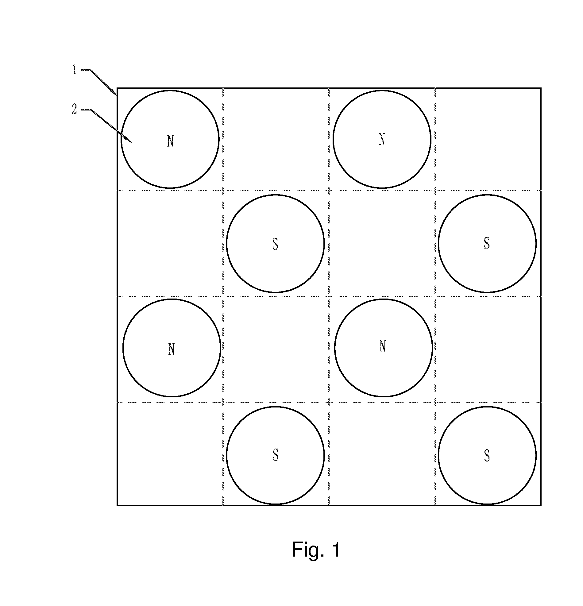
[0022]A magnetic suspension planar motor with a structure of superconductor excitation according to the embodiment 1 comprises: a primary structure, and a secondary structure; wherein an air gap is provided between the primary structure and the secondary structure; the primary structure comprises a primary base plate and armature windings; the primary base plate is in a shape of board; the armature windings are fixed on an air gap side of the primary base plate, wherein the air gap side is defined as a side adjacent to the air gap; the secondary structure comprises a secondary base plate 1, a cooling container, and 2 h2 superconducting magnets 2; the secondary base plate 1 is evenly divided into 2 h*2 h magnet cells, wherein h is a natural number; side lengths of the magnet cells are equal to a polar distance τp of a magnet array; the 2 h2 superconducting magnets 2 are respectively fixed in the magnet cells on the secondary base plate 1; the superconducting magnets 2 are not adjacen...

embodiment 2

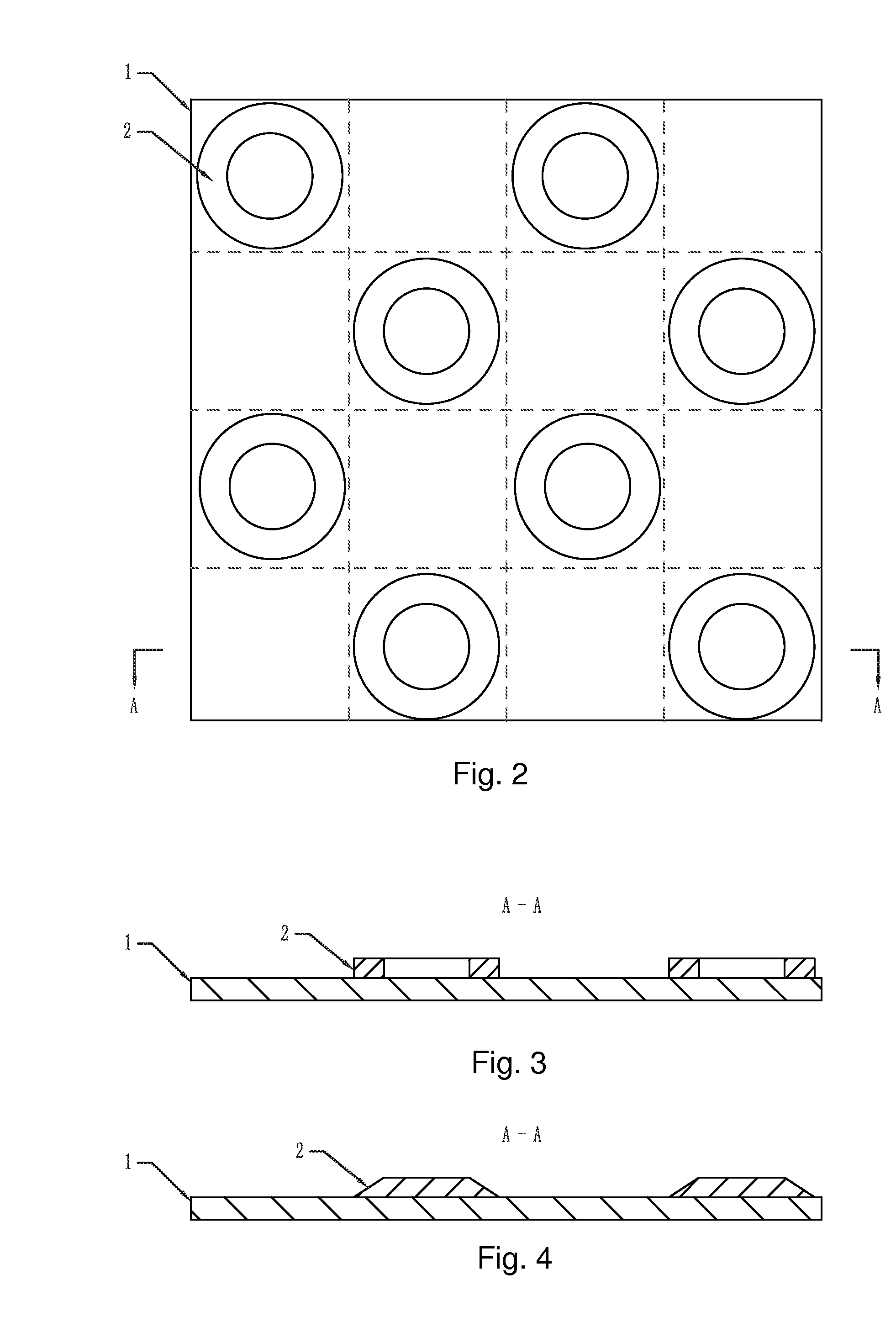
[0024]The magnetic suspension planar motor with the structure of superconductor excitation in the embodiment 2 is different from the magnetic suspension planar motor with the structure of superconductor excitation in the embodiment 1 in that, furthermore, the superconducting magnets 2 are embodied as superconductors, wherein the superconductor is in a shape of disc or annulus.

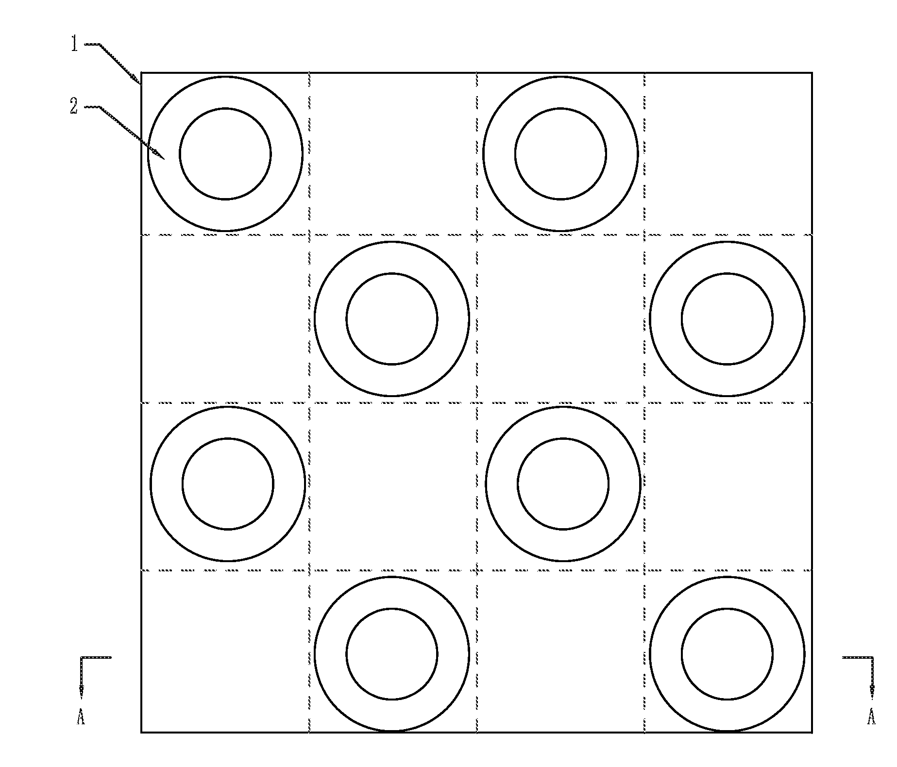
[0025]FIG. 1 shows a structure of the magnetic suspension planar motor with the structure of superconductor excitation as recited in the embodiment 2. In the structure, h=2, so the secondary base plate is divided into 4*4 magnet cells, and eight superconducting magnets 2 are provided in the secondary structure. The eight superconducting magnets 2 are arranged as FIG. 1. FIG. 2 is a sketch view illustrating the structure of the magnetic suspension planar motor with the structure of superconductor excitation, wherein the superconductors are in the shape of annulus.

embodiment 3

[0026]The magnetic suspension planar motor with the structure of superconductor excitation in the embodiment 3 is different from the magnetic suspension planar motor with the structure of superconductor excitation in the embodiment 1 in that, furthermore, the superconducting magnets 2 are embodied as superconductors, wherein the superconductor is in a shape of frustum of a cone, and a bottom of the frustum of the cone, which has a larger diameter, is fixedly connected with the secondary base plate.

[0027]FIG. 2 and FIG. 4 show a structure of the magnetic suspension planar motor with the structure of superconductor excitation as recited in the embodiment 3. In the structure, h=2, so the secondary base plate 1 is divided into 4*4 magnet cells, and eight superconducting magnets 2 are provided in the secondary structure. The eight superconducting magnets 2 are arranged as FIG. 1.


PUM

PropertyMeasurementUnit
primary structureaaaaaaaaaa
shapeaaaaaaaaaa
lengthsaaaaaaaaaa

Abstract

A magnetic suspension planar motor comprises a structure of superconductor excitation. A primary base plate is in a shape of board. Armature windings are fixed on an air gap side of the primary base plate. A secondary base plate in a secondary structure is evenly divided into 2 h*2 h magnet cells. 2 h2 superconducting magnets are respectively fixed in the magnet cells on the secondary base plate, which resembles a checkerboard pattern. The superconducting magnets are adjacent to each other, neither in a horizontal direction nor in a vertical direction. The superconducting magnets are magnetized parallelly, and magnetization directions of the superconducting magnets are perpendicular to a surface on an air gap side of the secondary base plate. The superconducting magnets in a same row or column have same magnetization directions, and the superconducting magnets in adjacent rows columns have contrary magnetization directions. A cooling container shields all of the superconducting magnets.

Description

CROSS REFERENCE OF RELATED APPLICATION[0001]This is a U.S. National Stage under 35 U.S.0 371 of the International Application PCT / CN2012 / 078081, filed Jul. 3, 2012, which claims priority under 35 U.S.C. 119(a-d) to CN201210019414.X filed Jan. 21, 2012.BACKGROUND OF THE PRESENT INVENTION[0002]1. Field of Invention[0003]The present invention relates to a magnetic suspension planar motor, and belongs to a field of electrical machine.[0004]2. Description of Related Arts[0005]Modern precision machining equipments and ultra-precision machining equipments urgently require planar driving devices having high response, high speed, and high precision, in machining, producing electronic products, mechanical handling, manufacturing instruments and meters for automation, even driving robots, etc. Usually the planar driving device is driven by rotating motors. Rotating motion is transferred to rectilinear motion by mechanical devices, such as belts and ball screw shafts. The mechanical device is c...

Claims


Application Information

Patent Timeline
Patent Type & Authority Applications(United States)
IPC IPC(8): H02K7/09H01F6/04H02K41/03
CPCH02K7/09H02K41/031H01F6/04H02K55/00H02K2201/18
Inventor KOU, BAOQUANLI, XIAOKUNZHANG, LUZHANG, HE
Owner HARBIN INST OF TECH
Why Eureka
Eureka Blog
Learn More