
Multiplexed diagnostic detection apparatus and methods

a diagnostic and multi-functional technology, applied in mechanical equipment, biomass after-treatment, laboratory glassware, etc., can solve the problems of inability to perform complex diagnostic analysis, etc., to achieve the effect of high-throughput, trained clinician-operated diagnostic analysis and high-throughput results

Active Publication Date: 2014-11-06
HANDYLAB
View PDF11 Cites 94 Cited by
  • Summary
  • Abstract
  • Description
  • Claims
  • Application Information

AI Technical Summary

Benefits of technology

The patent describes a microfluidic cartridge with multiple sample lanes that can amplify and detect target nucleic acids simultaneously. The cartridge includes an amplification chamber and a plurality of detection chambers downstream of the amplification chamber. Each sample lane has its own inlet, amplification valve, detection valve, and detection channel. The cartridge can also have a plurality of detection windows and a multiple-pipette head dispenser for simultaneous loading of samples. The detection heat sources and the amplification valves can be individually and separately controllable, and the detection chambers can have separate detection heat sources. The apparatus can also include a detector head with multiple detector pairs for detecting the presence of target nucleic acids. The technical effects of this invention include improved accuracy and sensitivity in detecting target nucleic acids and improved throughput in amplifying samples.

Problems solved by technology

At present, however, in vitro diagnostic analyses, no matter how routine, have become a bottleneck in patient care.
First, many diagnostic analyses can only be done with highly specialized equipment that is both expensive and only operable by trained clinicians.
This requires hospitals to send out samples for analyses to these locations, thereby incurring shipping costs and transportation delays, and possibly even sample loss or mishandling.
Second, the equipment in question is typically not available “on-demand” but instead runs in batches, thereby delaying the processing time for many samples as they must wait for a machine to reach capacity before they can be run.

Method used


Image

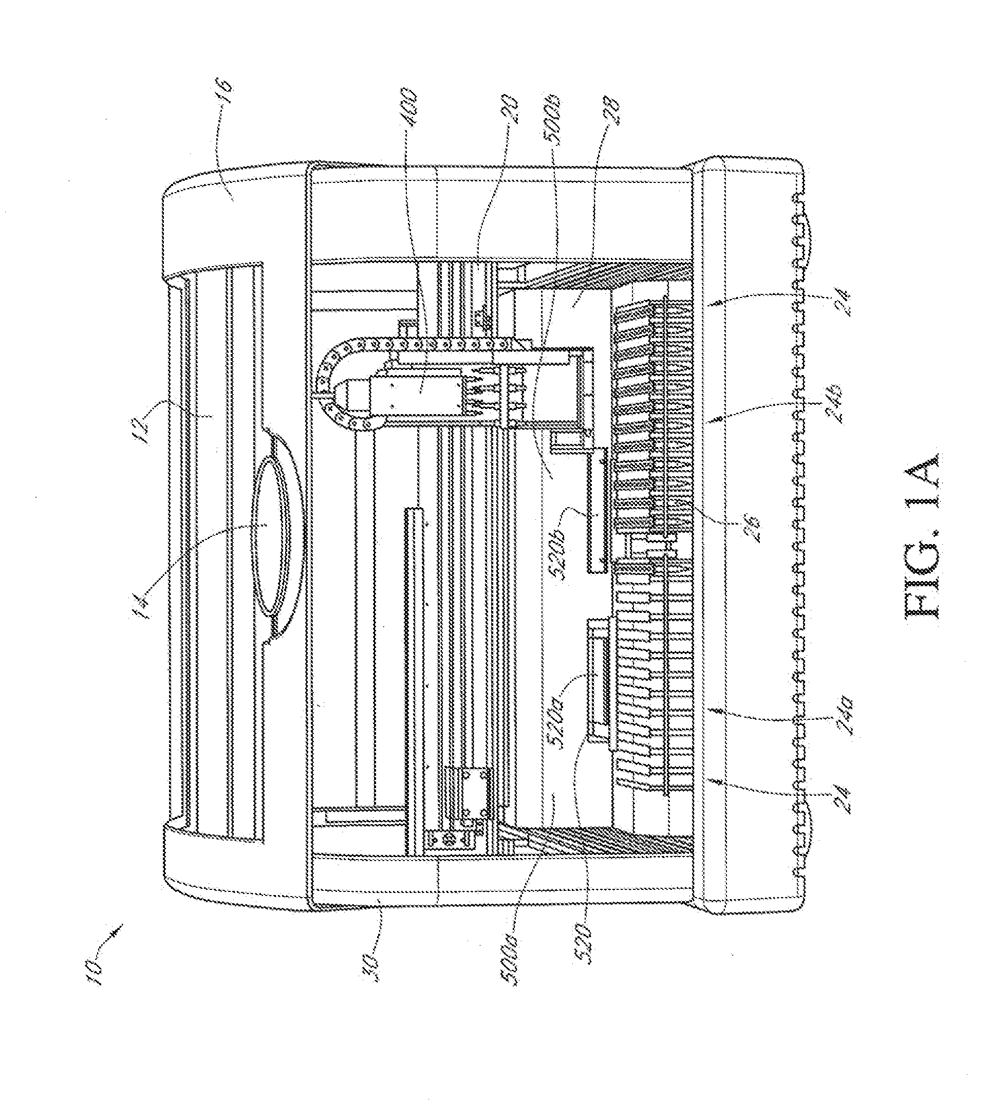
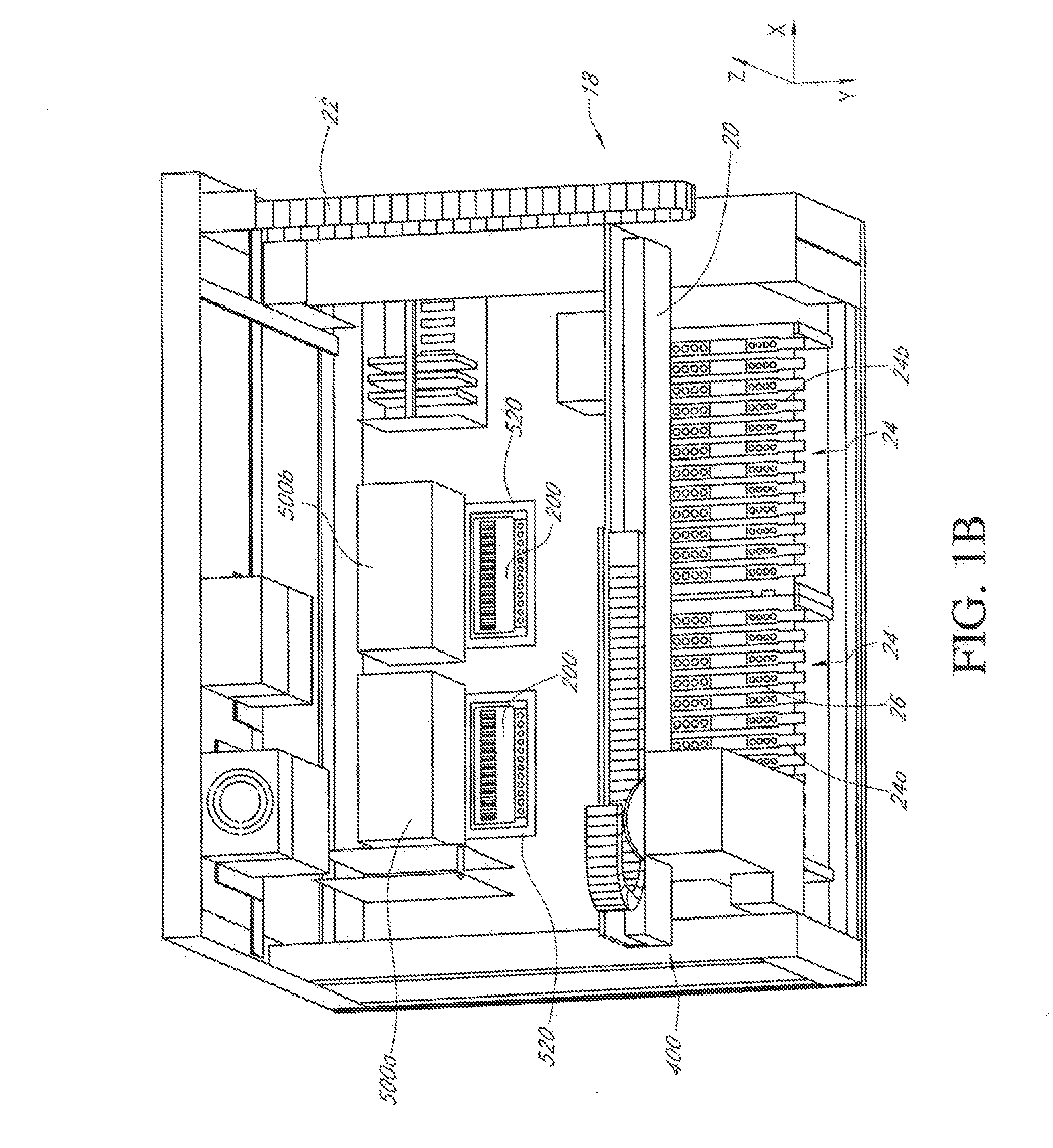
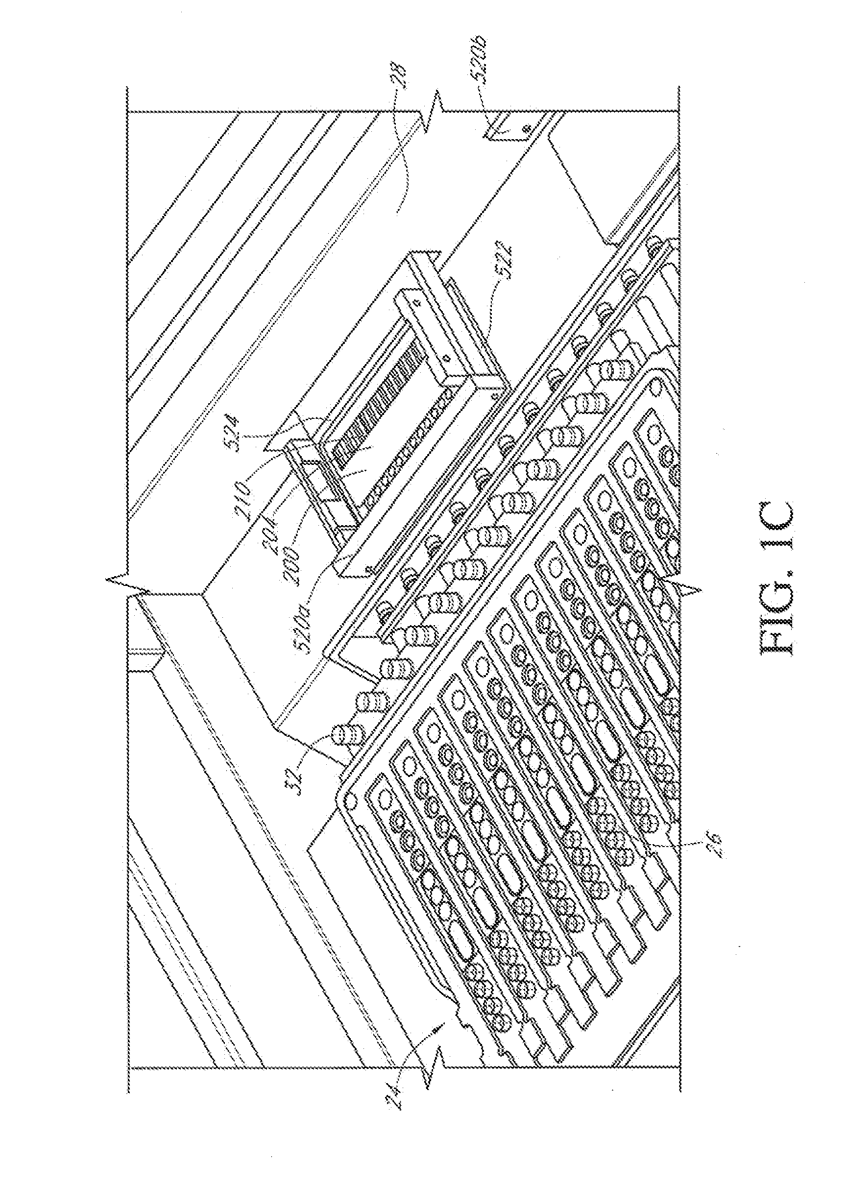
  • Multiplexed diagnostic detection apparatus and methods
  • Multiplexed diagnostic detection apparatus and methods
  • Multiplexed diagnostic detection apparatus and methods

Examples


Embodiment Construction

[0037]Before the embodiments are further described, it is to be understood that this invention is not limited to particular embodiments described, as such may, of course, vary. It is also to be understood that the terminology used herein is for the purpose of describing particular embodiments only, and is not intended to be limiting.

[0038]Where a range of values is provided, it is understood that each intervening value, to the tenth of the unit of the lower limit unless the context clearly dictates otherwise, between the upper and lower limit of that range and any other stated or intervening value in that stated range is encompassed within the embodiments. The upper and lower limits of these smaller ranges may independently be included in the smaller ranges and are also encompassed within the embodiments, subject to any specifically excluded limit in the stated range. Where the stated range includes one or both of the limits, ranges excluding either both of those included limits are...


PUM

PropertyMeasurementUnit
volumeaaaaaaaaaa
volumeaaaaaaaaaa
volumesaaaaaaaaaa

Abstract

Disclosed herein are devices configured for the amplification and detection of multiple targets from a sample, and methods of using the same. The devices disclosed herein comprise microfluidic cartridges have a first stage (amplification) and a second (detection) stage. The two-stage design of the cartridges enables testing for multiple targets within a sample, i.e., from a single nucleic acid amplification reaction. Methods for the amplification and detection of a plurality of target nucleic acids from a sample are also disclosed herein.

Description

CLAIM OF PRIORITY[0001]The present application is a continuation of International Application No. PCT / US2012 / 063091, filed on Nov. 1, 2012, which claims priority to U.S. Provisional Application Serial No. 61 / 556,032, filed Nov. 4, 2011. Each of the above applications is hereby incorporated by reference in its entirety.STATEMENT REGARDING FEDERALLY SPONSORED METHODS[0002]The research leading to the present invention was supported, at least in part, by a grant from the National Institutes of Health. Accordingly, the Government may have certain rights in the invention.TECHNICAL FIELD[0003]The apparatus and methods disclosed herein relate generally to the high-throughput, automated execution of nucleic acid based assays, such as Polymerase Chain Reaction (PCR) in a microfluidic cartridge.BACKGROUND[0004]The medical diagnostics industry is a critical element of today's healthcare infrastructure. At present, however, in vitro diagnostic analyses, no matter how routine, have become a bottl...

Claims


Application Information

Patent Timeline
Patent Type & Authority Applications(United States)
IPC IPC(8): C12Q1/68
CPCC12Q1/6806B01L3/5027B01L3/502723B01L3/502738B01L7/52B01L2200/0684B01L2200/10B01L2200/027B01L2300/0816B01L2400/0677B01L2400/06F16K99/0036F16K2099/0084
Inventor HANDIQUE, KALYAN
Owner HANDYLAB
Learn More