
Method for controlling regeneration of diesel particulate filter in construction machinery

a technology of construction machinery and diesel particulate filter, which is applied in the direction of machines/engines, electric control of exhaust treatment, separation processes, etc., can solve the problems of unavoidable discharge of exhaust gas, degrade performance, and degrade engine performan

Active Publication Date: 2014-11-13
DOOSAN INFRACORE CO LTD
View PDF9 Cites 0 Cited by
  • Summary
  • Abstract
  • Description
  • Claims
  • Application Information

AI Technical Summary

Benefits of technology

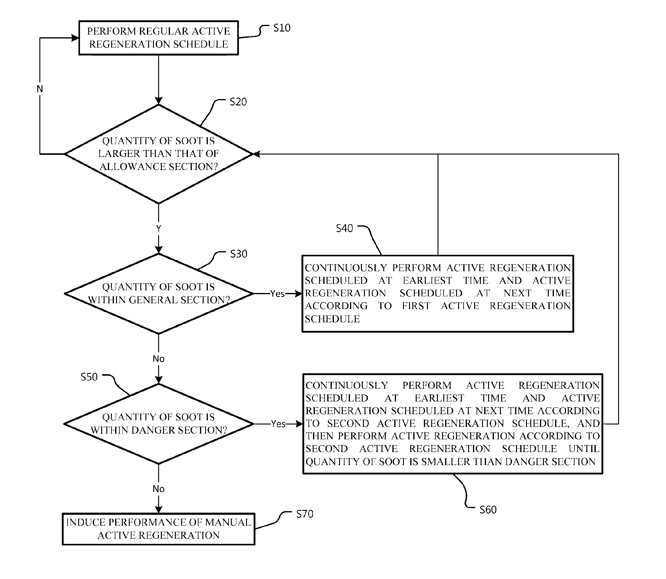
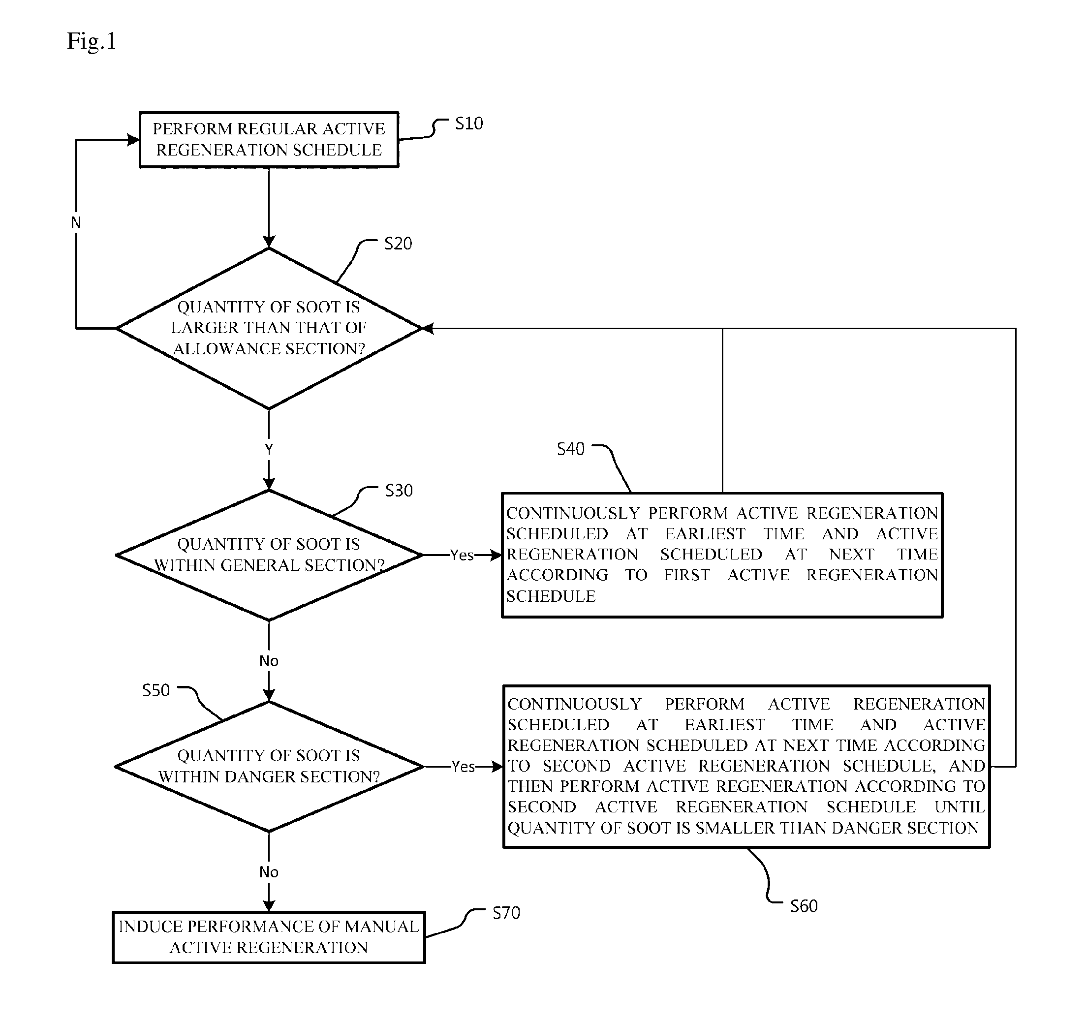
The regeneration controlling method for the diesel particulate filter of construction machinery described in this patent allows for timely and efficient regeneration of the filter, regardless of the type of machinery or work environment. This is done by changing the regeneration schedule based on the amount of soot present. The technical effect is improved emission control and reduced emissions from construction machinery.

Problems solved by technology

Exhaust gas is unavoidably discharged while driving the diesel engine, and the exhaust gas contains nitrogen oxide (NOx), of which the nitrogen oxide causes pollution by negatively affecting the atmospheric environment.
The soot degrades performance of the DPF and increases back pressure of the exhaust gas muffler, which degrades performance of the engine.
The active regeneration may be scheduled by a program, however, the active regeneration according to the schedule by the program is not efficient.
That is, in the related art, without considering the quantity of soot after performing the active regeneration, the active regeneration fails due to a shortage in the quantity of load or the quantity of temperature during performance of the regeneration or the active regeneration is performed only at a set time even after a starting is off, such that a problem of causing damage to the DPF is generated.

Method used


Image

  • Method for controlling regeneration of diesel particulate filter in construction machinery
  • Method for controlling regeneration of diesel particulate filter in construction machinery

Examples


Embodiment Construction

[0041]In the following detailed description, reference is made to the accompanying drawing, which form a part hereof. The illustrative embodiments described in the detailed description, drawing, and claims are not meant to be limiting. Other embodiments may be utilized, and other changes may be made, without departing from the spirit or scope of the subject matter presented here.

[0042]Advantages and characteristics of the present disclosure, and a method of achieving the advantages and characteristics will be clear with reference to an exemplary embodiment described below in detail together with the accompanying drawings.

[0043]Like reference numerals indicate like elements throughout the specification.

[0044]Further, the terms used in the description are defined considering the functions of the present disclosure and may vary depending on the intention or usual practice of a manufacturer. Therefore, the definitions should be made based on the entire contents of the present specificat...


PUM

PropertyMeasurementUnit
timeaaaaaaaaaa
temperatureaaaaaaaaaa

Abstract

The present disclosure relates to a method for controlling regeneration of diesel particulate filter in construction machinery. The regeneration controlling method for the diesel particulate filter of construction machinery according to the present disclosure includes: a first active generation operation of actively regenerating a diesel particulate filter (DPF) according to a predetermined first active regeneration schedule when a quantity of soot inside the DPF within is a predetermined allowance section; and a second active regeneration operation of actively regenerating the diesel particulate filter according to a second active regeneration schedule, which is different from the first active regeneration schedule, according to the quantity of soot when the quantity of soot exceeds the allowance section.

Description

CROSS-REFERENCE TO RELATED APPLICATION[0001]This Application is a Section 371 National Stage Application of International Application No. PCT / KR2012 / 010483, filed Dec. 5, 2012 and published, not in English, as WO 2013 / 115475 on Aug. 8, 2013.FIELD OF THE DISCLOSURE[0002]The present disclosure relates to a method for controlling regeneration of diesel particulate filter in construction machinery, and more particularly, to a method for controlling regeneration of diesel particulate filter in construction machinery in which a regeneration schedule of a particulate filter is actively changed according to the quantity of soot.BACKGROUND OF THE DISCLOSURE[0003]A technique of installing a diesel particulate filter and the like in an exhaust path of a diesel engine as an exhaust gas purifying device (post-processing device), and performing purifying processing on the exhaust gas discharged from the diesel engine through the diesel particulate filter and the like is known. The aforementioned ...

Claims


Application Information

Patent Timeline
Patent Type & Authority Applications(United States)
IPC IPC(8): F01N9/00B01D46/00F01N3/023
CPCF01N9/002F01N3/0232B01D46/0057F01N2900/1606Y02T10/40F01N3/023F01N9/00B01D46/66
Inventor YUN, HONG CHEOLCHOI, YUN JUNG
Owner DOOSAN INFRACORE CO LTD
Learn More