Combustion control device and control method for internal combustion engine

a combustion control device and control method technology, applied in the direction of electric control, ignition automatic control, machines/engines, etc., can solve the problems of increased maintenance cost, inability to provide high efficiency operation settings, and damage to internal combustion engines, so as to reduce the amount of deposit deposition, reduce running cost and maintenance cost, the effect of simple and low-cost means

Active Publication Date: 2014-11-13
MITSUBISHI HEAVY IND LTD
View PDF7 Cites 2 Cited by
  • Summary
  • Abstract
  • Description
  • Claims
  • Application Information

AI Technical Summary

Benefits of technology

[0032]According to the present invention, it is possible to keep the exhaust gas property not greater than the regulation value and also to reduce the running cost and the maintenance cost for removing the deposit of the internal combustion engine by detecting the deposit deposition amount inside the cylinder accurately with a simple and low-cost means and performing such operation that reduces the deposit deposition amount. The present invention can be employed for an internal combustion in general, such as the gas engine, the diesel engine, and the gasoline engine.

Problems solved by technology

Therefore, even if some abnormality has occurred for a certain cylinder and the deposit is markedly increased, such abnormality cannot be detected promptly, which may lead to troubles such as damage to the internal combustion engine.
Accordingly, it is not always possible to provide an operation setting with high efficiency.
Thus, unnecessary maintenance is performed for an internal combustion engine with the operation conditions that produce a small amount of deposit even for the engine of the same type, causing extra maintenance cost.
In contrast, for an engine with the operation conditions that produce a large amount of deposit (such as an engine often performing low-load operation), there is a possibility that the timing for removing the deposit is delayed and the exhaust gas exceeds the regulation value.

Method used


Image

  • Combustion control device and control method for internal combustion engine
  • Combustion control device and control method for internal combustion engine
  • Combustion control device and control method for internal combustion engine

Examples


first embodiment

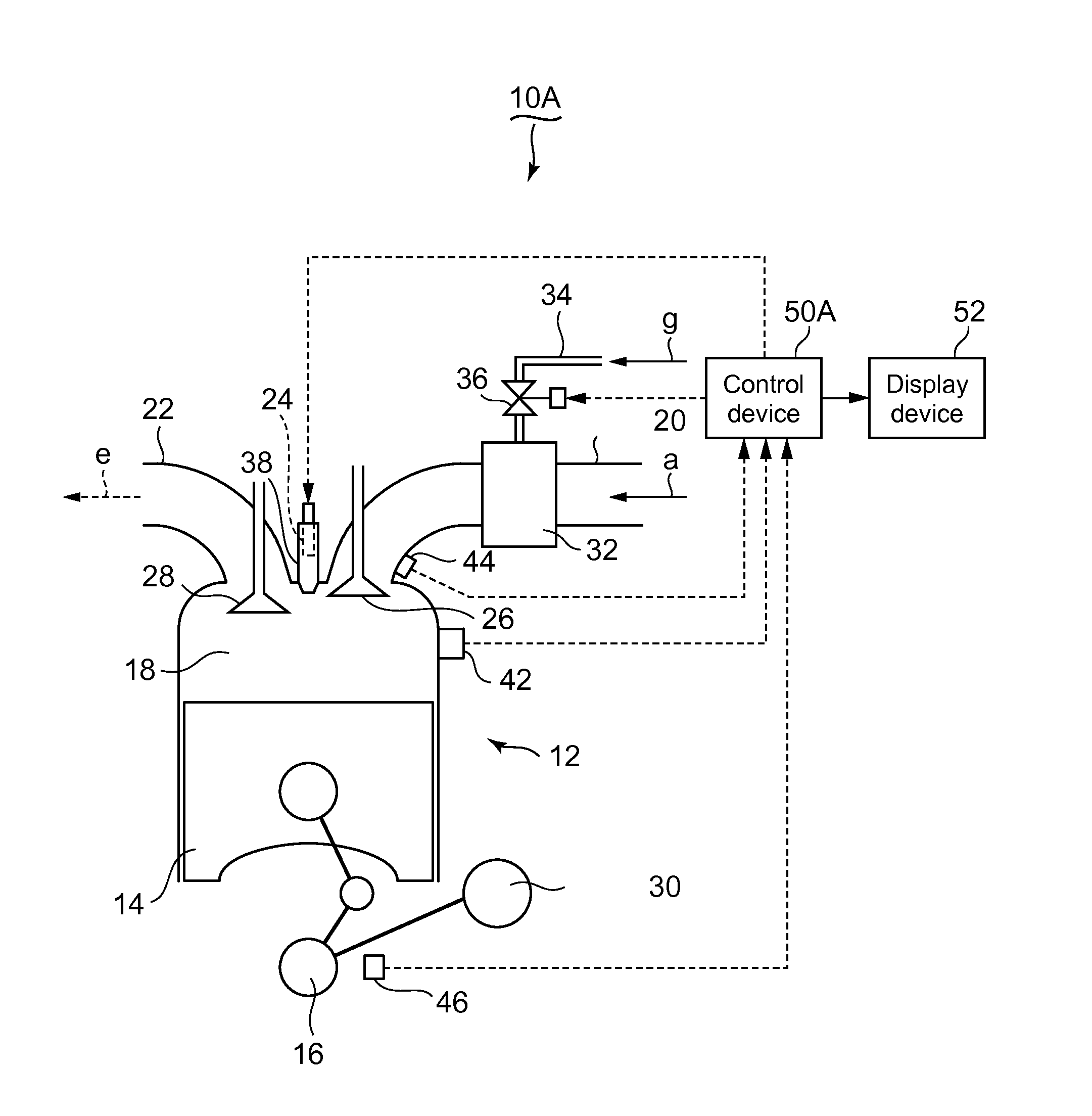
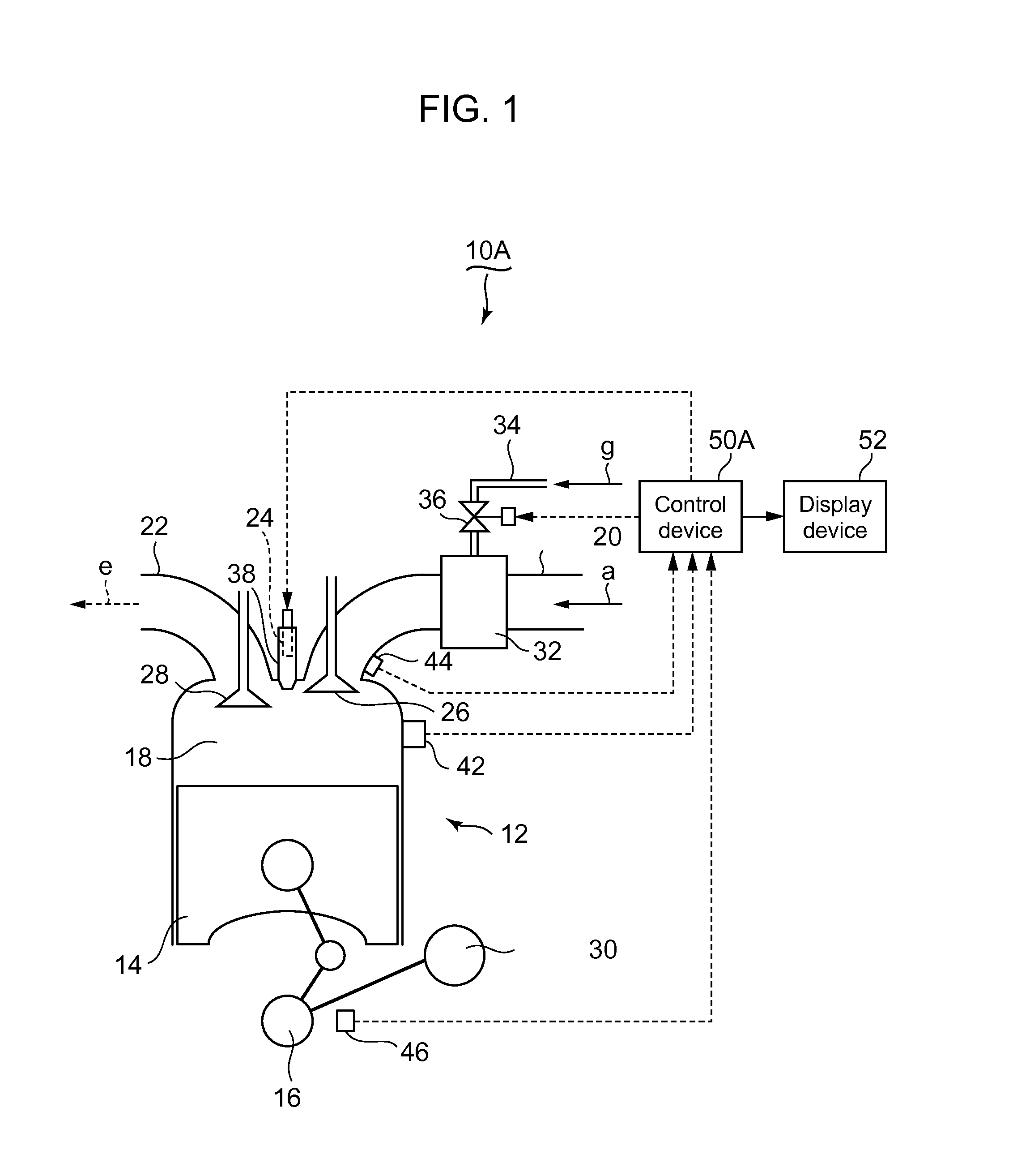
[0047]The first embodiment where the present invention is employed for a stationary gas engine will be described in reference to FIGS. 1 to 6. In FIG. 1, illustrated is a cylinder 12 included in a stationary gas engine 10A having a plurality of cylinders. In FIG. 1, a piston 14 is reciprocated by a crank shaft 16 inside the cylinder 12. A combustion chamber 18 is formed above the piston 14. An air supply pipe 20 and an air discharge pipe 22 are connected to the cylinder head, an auxiliary chamber 38 is provided for the central part of the cylinder head, and an ignition device 24 is provided inside the auxiliary chamber 38. An air supply valve 26 is provided for the opening of the air supply pipe 20, and an air discharge valve 28 is provided for the opening of the air discharge pipe 22.

[0048]A generator 30 is driven by rotation of the crank shaft 16. A gas injection device 32 is provided halfway into the air supply pipe 20 for injecting fuel gas “g” to the air “a” which flows inside ...

second embodiment

[0065]Next, the second embodiment of the present invention will be described in reference to FIGS. 7 to 9. The present embodiment is an example employed for a stationary gas engine having the configuration similar to that of the first embodiment. FIG. 7 illustrates the configuration of the control device 50B of the present embodiment. The control device 50B further includes a warning device 54 and an engine stop device 56 in addition to the configuration of the control device 50A of the first embodiment. The warning device 54 is provided for a place such as the monitoring room where information can be delivered to the operators and other relevant persons.

[0066]The combustion control procedures of the control unit 50B will be described in reference to FIG. 8. First, similarly to the first embodiment, the actual compression ratio ε in the cylinder 12 is calculated from the compression pressure Pc, the air supply pressure Ps and the air supply temperature Ts (S20). Next, similarly to t...

third embodiment

[0070]Subsequently, the third embodiment of the present invention will be described in reference to FIG. 10. In the present embodiment, the moving average of the detected result of the actual compression ratio ε is used for reducing the effect of the change in the detected result of each operation cycle (each compressions stroke).

[0071]As shown in FIG. 10, first, the cylinder pressure before ignition Pc is detected (S40). Next, the detected value deviation ΔPc between the detected cylinder pressure before ignition Pc1 and the moving average of cylinder pressure before ignition taken up to the previous calculation cycle, Pc2, is calculated (S42). This detected result deviation ΔPc is compared to the threshold value (S44). When the detected value deviation ΔPc≦the threshold value, the currently detected cylinder pressure before ignition Pc1 is used for calculating the moving average including the cylinder pressure before ignition Pc1 (S46). On the other hand, when the detected value d...


PUM


Abstract

In a control device 50A, an actual compression ratio calculation unit 502 calculates an actual compression ratio ε from an air supply pressure Ps, a cylinder pressure before ignition Pc and an air supply temperature Ts. A deposit deposition estimation unit 504 determines the deposit deposition state of a combustion chamber 18 from a deviation Δε between the actual compression ratio ε and a design compression ratio ε′. When the deviation Δε exceeds a threshold value, ignition timing or air-fuel ratio being operation conditions of an internal combustion engine is corrected based on a correction map 508 so as to suppress deterioration of exhaust gas.

Description

TECHNICAL FIELD[0001]This invention relates to a combustion control device and a control method for an internal combustion engine, which are capable of determining the deposition state of the carbon deposit in the combustion chamber and switching to the operation that suppresses deterioration of the exhaust gas property based on the deposition state.BACKGROUND ART[0002]In an internal combustion engine, generally, deposit such as the carbon deposit being residue of fuel or lubricant oil is accumulated inside the combustion chamber with the prolonged operation. For instance, the deposit is accumulated on the piston surface, the fuel injection valve, and the like. As a result, the compression ratio increases, causing NOX, CO, HC, etc in the exhaust gas to show an increasing trend. FIG. 12 is a diagram of a relation between deposition of the deposit inside the combustion chamber (travel distance) and NOX in the exhaust gas in an internal combustion engine provided for an automobile. As ...

Claims


Application Information

Patent Timeline
Patent Type & Authority Applications(United States)
IPC IPC(8): F02P5/04F02D41/30
CPCF02P5/045F02D41/30F02D35/023F02D2200/0406F02D41/0087F02D41/22F02D41/0027F02D2200/0414F02D19/023F02P5/151F02P5/1512F02P5/153F02D2041/227F02D2041/228Y02T10/40F02P5/1502
Inventor ANDOU, JUNNOSUKE
Owner MITSUBISHI HEAVY IND LTD
Why Eureka
Try Eureka