
Carrier substrate and manufacturing method thereof

Active Publication Date: 2014-11-13
UNIMICRON TECH CORP
View PDF5 Cites 4 Cited by
  • Summary
  • Abstract
  • Description
  • Claims
  • Application Information

AI Technical Summary

Benefits of technology

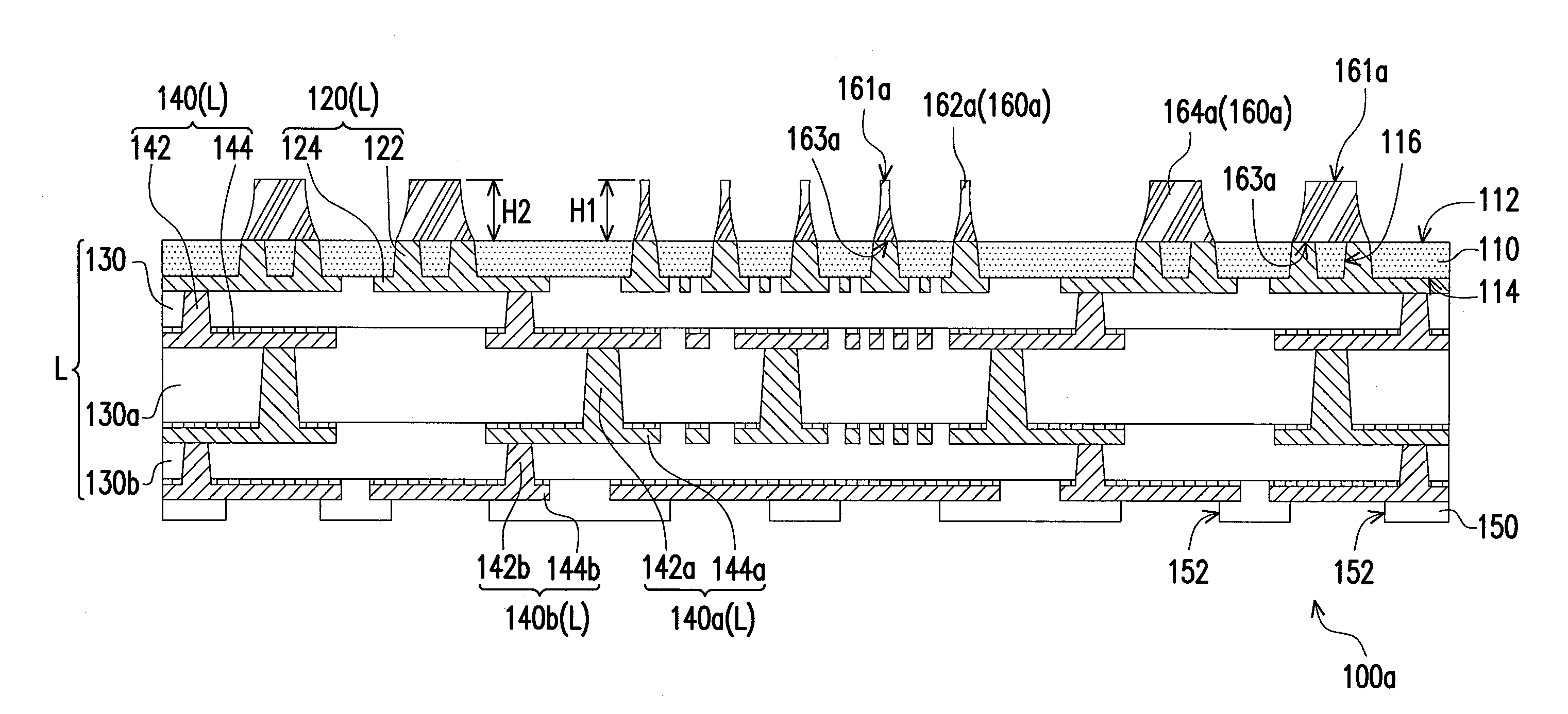
The invention provides conductive towers with uniform height and coplanarity, which improves the joining reliability between the towers and other components, such as packaging and chips. This is achieved by using a patterned dry film as an etching mask to etch second copper foil layers with uniform thickness.

Problems solved by technology

However, since a plurality of independent copper pillars are formed on a circuit layer exposed by a patterned dry film by electroplating through the patterned dry film as an electroplating mask, the copper pillars formed are easily prone to have a poor height uniformity or coplanarity therebetween due to process variation.
As a result, in the subsequent, when the carrier substrate is electrically connected with the package body and / or the chip through the copper pillars, a joining reliability between the copper pillars and the package body or the chip is reduced easily.

Method used


Image

  • Carrier substrate and manufacturing method thereof
  • Carrier substrate and manufacturing method thereof
  • Carrier substrate and manufacturing method thereof

Examples


Embodiment Construction

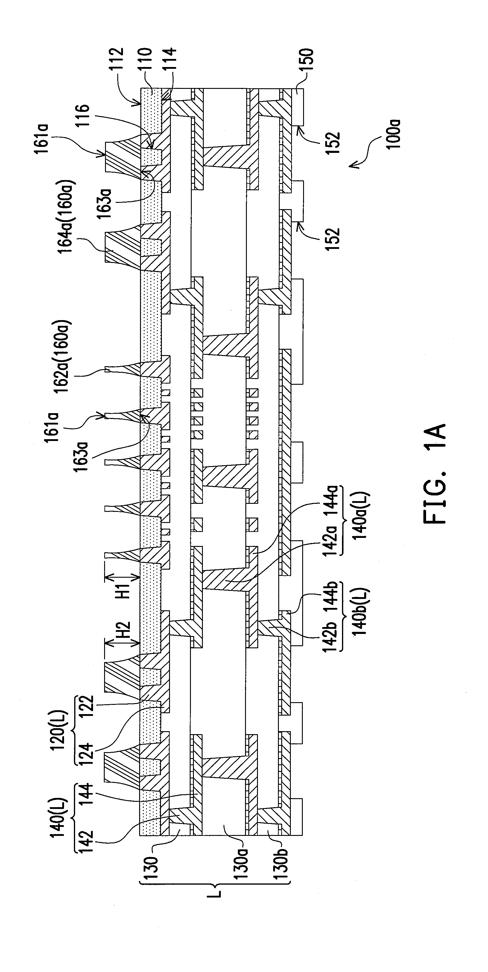
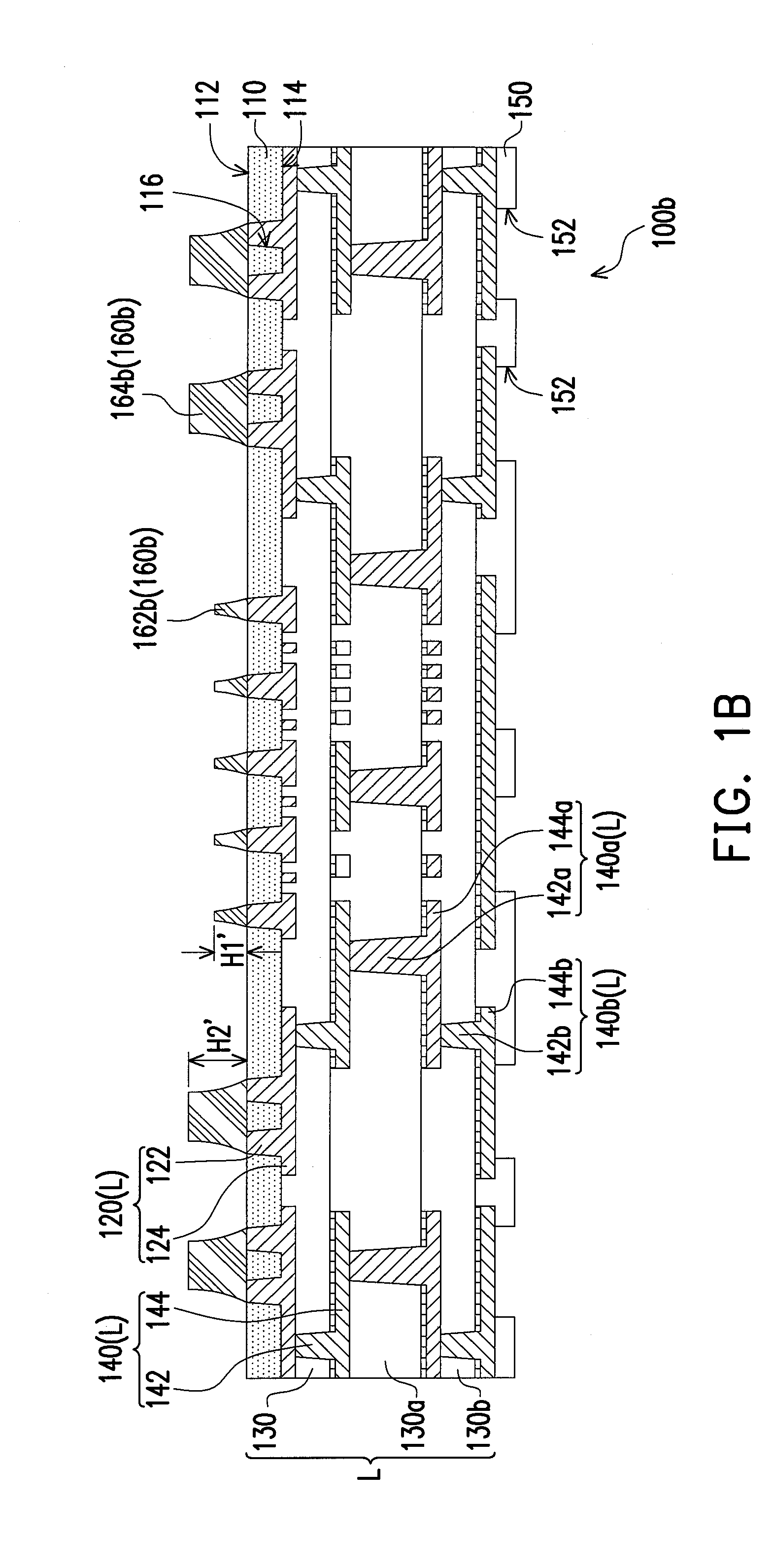
[0028]FIG. 1A is schematic cross-sectional view illustrating a carrier substrate according to an embodiment of the invention. Referring to FIG. 1A, in the present embodiment, the carrier substrate 100a includes an insulation layer 110, a circuit structure layer L, a solder resist layer 150 and a plurality of conductive towers 160a. In detail, the insulation layer 110 has a first surface 112 and a second surface 114 relative to each other and a plurality of first openings 116 extending from the first surface 112 to the second surface 114. Herein, as shown in FIG. 1A, an aperture of the first openings 116 of the present embodiment gradually increases from the first surface 112 of the insulation layer 110 towards the second surface 114. The conductive towers 160a are disposed on the first surface 112 of the insulation layer 110, wherein each of the conductive towers 160a has a top surface 161a and a bottom surface 163a relative to each other, and a diameter of each of the conductive to...


PUM


Abstract

A carrier substrate includes an insulation layer, conductive towers and a circuit structure layer. A diameter of each of the conductive towers is increased gradually from a top surface to a bottom surface, and the conductive towers include first conductive towers and second conductive towers surrounding the first conductive towers. The circuit structure layer is disposed on the insulation layer and includes at least one dielectric layer, at least two circuit layers and first conductive vias. Each of the second conductive towers correspondingly connects to at least two of the first conductive vias, and each of the first conductive towers correspondingly connects to one of the first conductive vias. An interface exists between the first conductive vias and the first and the second conductive towers.

Description

CROSS-REFERENCE TO RELATED APPLICATION[0001]This application claims the priority benefit of Taiwan application serial no. 102116745, filed on May 10, 2013. The entirety of the above-mentioned patent application is hereby incorporated by reference herein and made a part of this specification.BACKGROUND OF THE INVENTION[0002]1. Field of the Application[0003]The invention is directed to a substrate and a manufacturing method thereof, and more particularly, to a carrier substrate adapted to carrying components and a manufacturing method thereof[0004]2. Description of Related Art[0005]In general, copper pillars connecting with a package body and copper pillars connecting with a chip are formed on a conventional carrier substrate by performing an electroplating process twice. However, since a plurality of independent copper pillars are formed on a circuit layer exposed by a patterned dry film by electroplating through the patterned dry film as an electroplating mask, the copper pillars fo...

Claims


Application Information

Patent Timeline
IPC IPC(8): H05K1/11H05K3/40
CPCH05K1/11H05K3/40H05K3/06H05K3/4007H05K2201/0367H05K2201/0979H05K2203/0369H05K2203/0376H01L2924/0132H01L2924/0133H01L24/16H01L2224/16225H01L2924/12042H05K3/4682H01L2924/01029H01L2924/01047H01L2924/0105H01L2924/00H01L21/67265H01L21/673H01L21/67346H01L21/67763H01L21/6779
Inventor LIN, CHUN-TING
Owner UNIMICRON TECH CORP
Learn More