Current-to-voltage converter and electronic apparatus thereof

a current-to-voltage converter and electronic device technology, applied in power conversion systems, differential amplifiers, amplifiers with semiconductor devices/discharge tubes, etc., can solve the problems of insufficient voltage vout falling speed, current-to-voltage conversion error, etc., to enhance the rising or falling speed of output voltage, wide output swing, and high input range

Active Publication Date: 2014-11-13
ILI TECHNOLOGY CORPORATION
View PDF2 Cites 10 Cited by
  • Summary
  • Abstract
  • Description
  • Claims
  • Application Information

AI Technical Summary

Benefits of technology

[0014]To sum up, the current-to-voltage converter provided by the exemplary embodiment of the present disclosure can have the high input range and wide output swing by using the current tracking bias circuit and the voltage clamp bias circuit. In addition, the current-to-voltage unit of the current-to-voltage converter can have the current control device to enhance the rising or falling speed of the output voltage of the current-to-voltage converter. Furthermore, the voltage clamp bias circuit can further maintains the drain-source voltage of the transistor in the current-to-voltage unit with a constant voltage value, so as to reduce the effect which the channel length modulation effect of the transistor affects the output voltage of the current-to-voltage converter.

Problems solved by technology

However, the operation bandwidth of the operation amplifiers OP1 and OP2 may decrease the current tracking speeds of the currents flowing the P-type transistors P2, P4, and the N-type transistors N5, N3, such that the transient speed of the voltage Vout of the output end may be too slow to cause the current-to-voltage (Iin-to-Vout) conversion error, i.e. the rising or falling speed of the currents flowing the P-type transistors P2, P4, and the N-type transistors N5, N3 may be slow unexpectedly, and the rising or falling speed of the voltage Vout is not fast enough.

Method used


Image

  • Current-to-voltage converter and electronic apparatus thereof
  • Current-to-voltage converter and electronic apparatus thereof
  • Current-to-voltage converter and electronic apparatus thereof

Examples


Embodiment Construction

[0024]Reference will now be made in detail to the exemplary embodiments of the present disclosure, examples of which are illustrated in the accompanying drawings. Wherever possible, the same reference numbers are used in the drawings and the description to refer to the same or similar parts.

Exemplary Embodiment of Current-to-Voltage Converter

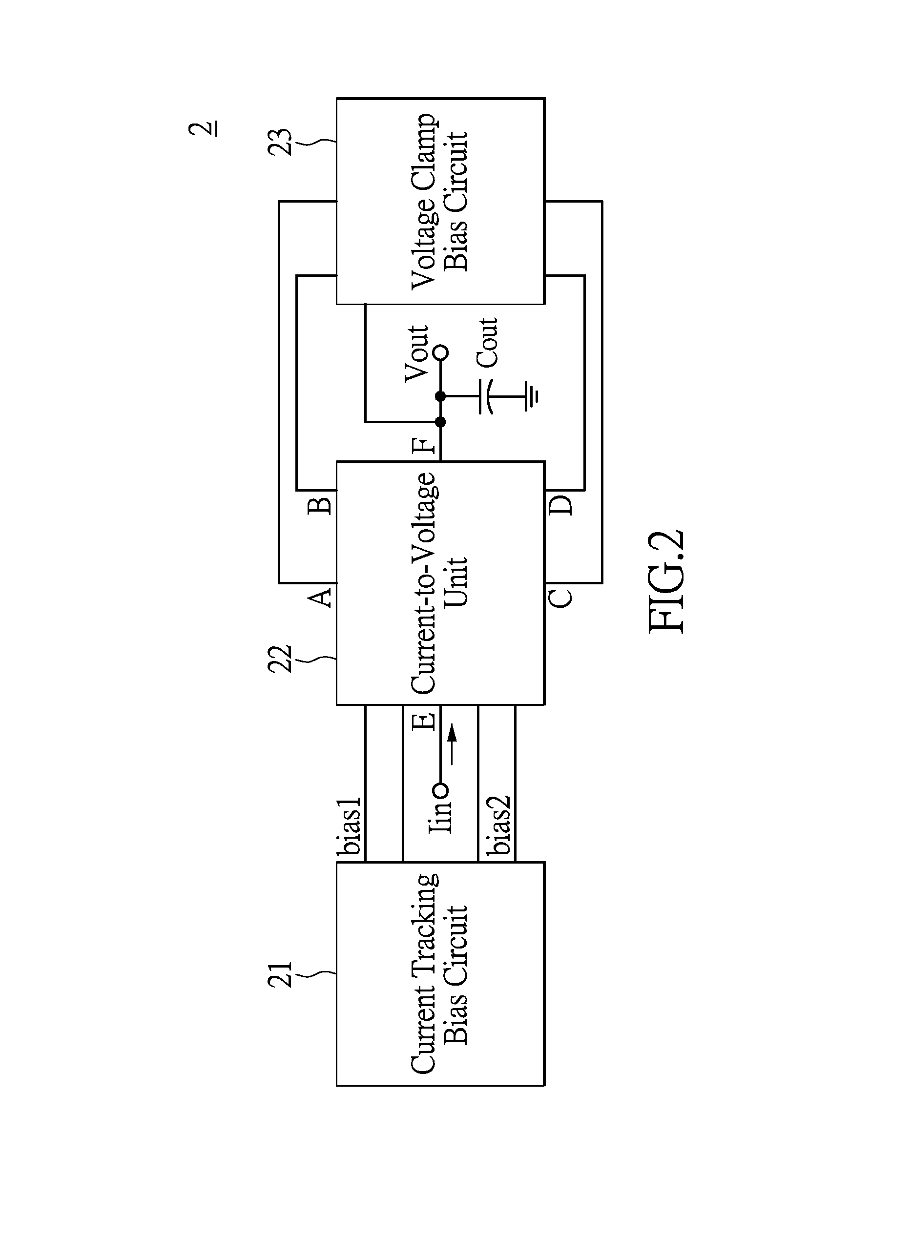
[0025]Referring to FIG. 2, FIG. 2 is a block diagram of a current-to-voltage converter according to an exemplary embodiment of the present disclosure. The current-to-voltage converter 2 comprises a current tracking bias circuit 21, a current-to-voltage unit 22, a voltage clamp bias circuit 23, and an output capacitor Cout. Two output ends of the current tracking bias circuit 21 are connected to two bias ends of the current-to-voltage unit 22, and two ends of the current tracking bias circuit 21 are connected to two ends of the current-to-voltage unit 22 respectively. The four ends A through D of the current-to-voltage unit 22 are respectively co...


PUM


Abstract

A current-to-voltage converter which is used to receive an input current and to generate an output voltage accordingly comprises a current tracking bias circuit, a current-to-voltage unit, and a voltage clamp bias circuit. The current tracking bias circuit generates a first bias according to the input current. The current-to-voltage unit receives the first bias and the input current, and generates the output voltage according to the input current, wherein the first bias determines a range of the input current, the current-to-voltage unit has a first current control device, and the first current control device changes a current conduction level thereof in response to the first bias, such that a rising or falling speed of the output voltage is enhanced. The voltage clamp bias circuit clamps voltage levels of two ends where the voltage clamp bias circuit is connected to the current-to-voltage unit.

Description

BACKGROUND[0001]1. Technical Field[0002]The present disclosure is related to a current-to-voltage converter, and in particular to, a single stage current-to-voltage converter with a high input range and a wide output swing, and the electronic apparatus using the current-to-voltage converter.[0003]2. Description of Related Art[0004]Currently, an electronic apparatus usually has a current-to-voltage converter, and the current-to-voltage converter can convert the current to the voltage, and transmit the converted voltage to the other function circuit of the electronic apparatus, such that the function circuit can receive the voltage, and execute a corresponding function according to the voltage.[0005]Please refer to FIG. 1, FIG. 1 is circuit diagram of a conventional current-to-voltage converter. The conventional current-to-voltage converter 1 comprises a first current-to-voltage unit 11, a second current-to-voltage unit 12 and an output capacitor Cout, and has an input end at an end E...

Claims


Application Information

Patent Timeline
Patent Type & Authority Applications(United States)
IPC IPC(8): H02M1/00
CPCH02M1/00H03F3/345
Inventor CHENG, CHIH-JENHSU, CHENG-CHUNG
Owner ILI TECHNOLOGY CORPORATION
Why Eureka
Try Eureka