Method and arrangement for removing ground clutter

Active Publication Date: 2014-11-13
EIGENOR
View PDF14 Cites 17 Cited by
  • Summary
  • Abstract
  • Description
  • Claims
  • Application Information

AI Technical Summary

Benefits of technology

[0012]Statistical analysis can be applied to derive a general form of an optimal digital filter for removing ground clutter. However, ground clutter removal is most advantageously switched on only for those measurement volumes that actually do contain ground clutter. Among those, the filtering should be accomplished with a different emphasis depending on how large the effect of the ground clutter was. This task can be a

Problems solved by technology

However, not all ground clutter comes from exactly stationary objects.
However, the cost is the modest signal-to-noise ratio of a Multi-PRT radar in the frequency domain.
This would mean that the Multi-PRT radar could only recover from at most 25 dB of grou

Method used


Image

  • Method and arrangement for removing ground clutter
  • Method and arrangement for removing ground clutter
  • Method and arrangement for removing ground clutter

Examples


Embodiment Construction

[0035]The speed of light is approximately 300 m / μs and the microwave pulse travels at that speed but the echo has to travel all the way back to the antenna from an increasing distance. The measured range at which observations are made thus increases by 150 m / μs, not 300 m / μs.

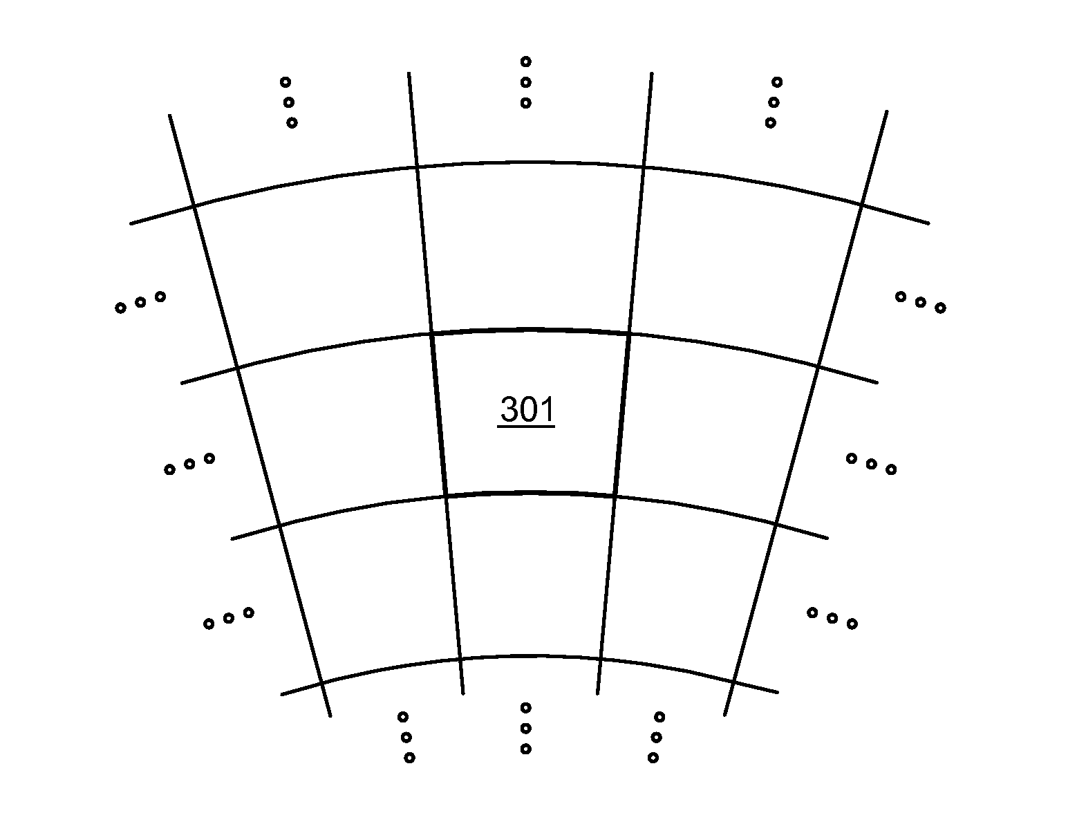
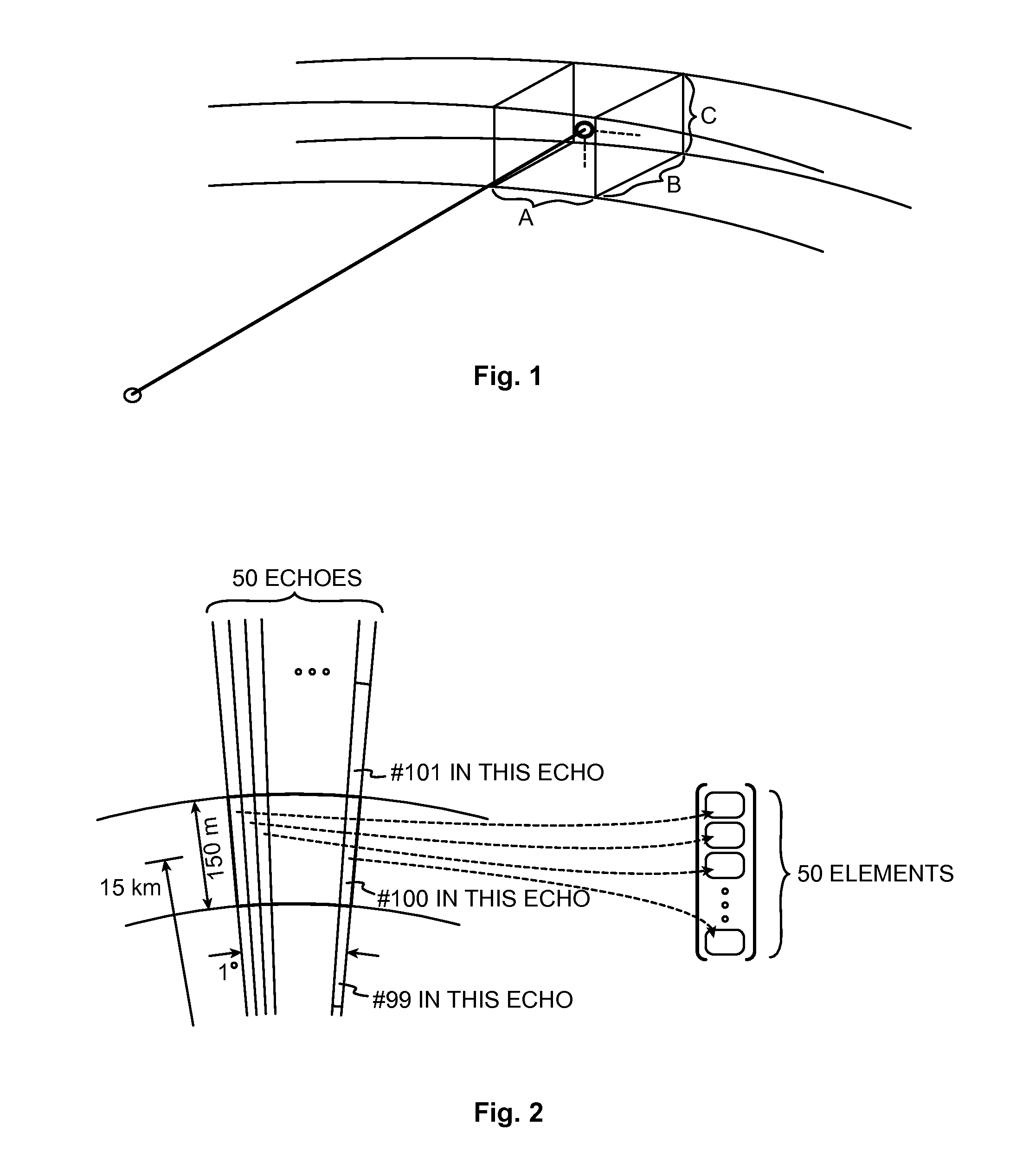
[0036]Weather radar measurements aim at characterizing the meteorological phenomena up to a certain maximum range from the radar transceiver with a certain spatial resolution. FIG. 1 illustrates how a measured point actually corresponds to a volume. The width A of the volume is the selected azimuthal output resolution, which is for example one degree. Its length B is the range resolution, and its height C equals the width of the antenna beam in the vertical direction.

[0037]The data coming from the receiver is a stream of complex numbers that represents the echo from a pulse the radar has sent. The range resolution is defined by the data rate, which can be for example one MHz. This translates to one complex numbe...


PUM


Abstract

A digital radar receiver generates the input signal which is a stream of complex numbers. The input signal is rearranged and sorted by measurement volumes, resulting in Doppler data vectors. Doppler data vectors are filtered using a number of different digital filters. The output Doppler data vectors of the filters together with the original Doppler data vector are the candidate signals. Each candidate signal is analyzed using several criteria in order to find the one signal which is most likely to be caused by precipitation and has the ground clutter removed by the filtering. The selected signal is then used to calculate the meteorological products. The selected signal is also used to derive a velocity value or velocity distribution while taking into account the effects of the filtering performed earlier.

Description

1 TECHNICAL FIELD[0001]The present invention is generally related to the technology of processing the signals received in a remote sensing apparatus. Especially the invention is concerned with the task of removing unwanted signal components, such as ground clutter, from the signal received in a remote sensing apparatus such as a pulse radar.2 BACKGROUND OF THE INVENTION[0002]Clutter, or more specifically ground clutter, is the general designation of signal contamination in the form of echoes or reflections that a remote sensing instrument, such as a weather radar for example, gets from trivial, unwanted, stationary targets. A major task of a weather radar is to measure the reflectivity and speed (relative to the radar station) of airborne precipitation, i.e. raindrops and ice particles, in which task strong echoes from stationary obstacles are a nuisance. A number of signal processing approaches have been developed to remove ground clutter, while simultaneously salvaging as much of ...

Claims


Application Information

Patent Timeline
IPC IPC(8): G01S13/95
CPCG01S13/95G01S13/227G01S13/5244G01S13/532G01S13/951Y02A90/10
Inventor SIERWALD, JORN
Owner EIGENOR
Why Eureka
Try Eureka