System and method for on-line measuring a burden surface in a blast furnace

a technology for blast furnaces and burden surfaces, applied in television systems, furnaces, monitoring devices, etc., can solve the problems of complex computing systems, complex processing of obtained data, and inability of operators to directly observe in-furnace information, so as to simplify laser emitter protective measures, reduce system costs, and minimize system volume

Inactive Publication Date: 2014-11-13
GAO ZHENGKAI +4
View PDF9 Cites 8 Cited by
  • Summary
  • Abstract
  • Description
  • Claims
  • Application Information

AI Technical Summary

Benefits of technology

[0020]1) As compared with the Chinese Patent ZL200610089415.6, the number of the actual detection points on the burden surface using the present system and method for on-line measuring a burden surface in a blast furnace is only limited by laser scanning speed and a sampling frequency of the video camera. It is irrelevant to the number of the employed laser emitters. On the one hand, this may substantially reduce the cost of the system, and on the other hand, massive actual detection data may be generated from a large number of actual d

Problems solved by technology

Hence, operators can not directly observe in-furnace information, e.g., burden surface in the furnace, charging process and operation states of in-furnace devices, and he has to deduce the in-furnace information from values of conventional detecting meters detecting parameters such as temperature, pressure, flow rate and so on.
However, these detections require applying complicated detecting and receiving devices and complicated computing system to process obtained data.
In addition, those data all are distance information which needs to be restructured to form simulated image, and “WYSIWYG (What You See Is What You Get)” observation images may not be directly obtained.
However, during furnace charging process or in a state of a lower temperature of the burden

Method used


Image

  • System and method for on-line measuring a burden surface in a blast furnace
  • System and method for on-line measuring a burden surface in a blast furnace
  • System and method for on-line measuring a burden surface in a blast furnace

Examples


Embodiment Construction

[0025]The present invention will be further described in detail with reference to drawings and embodiments.

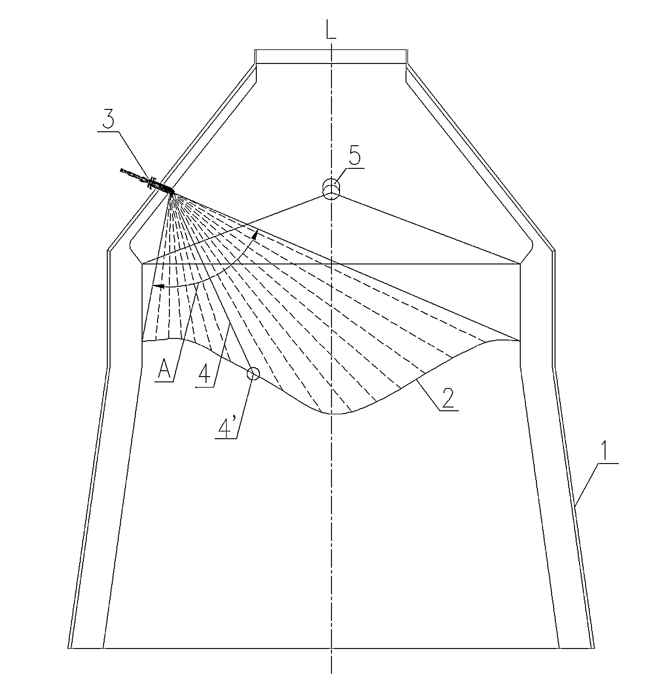
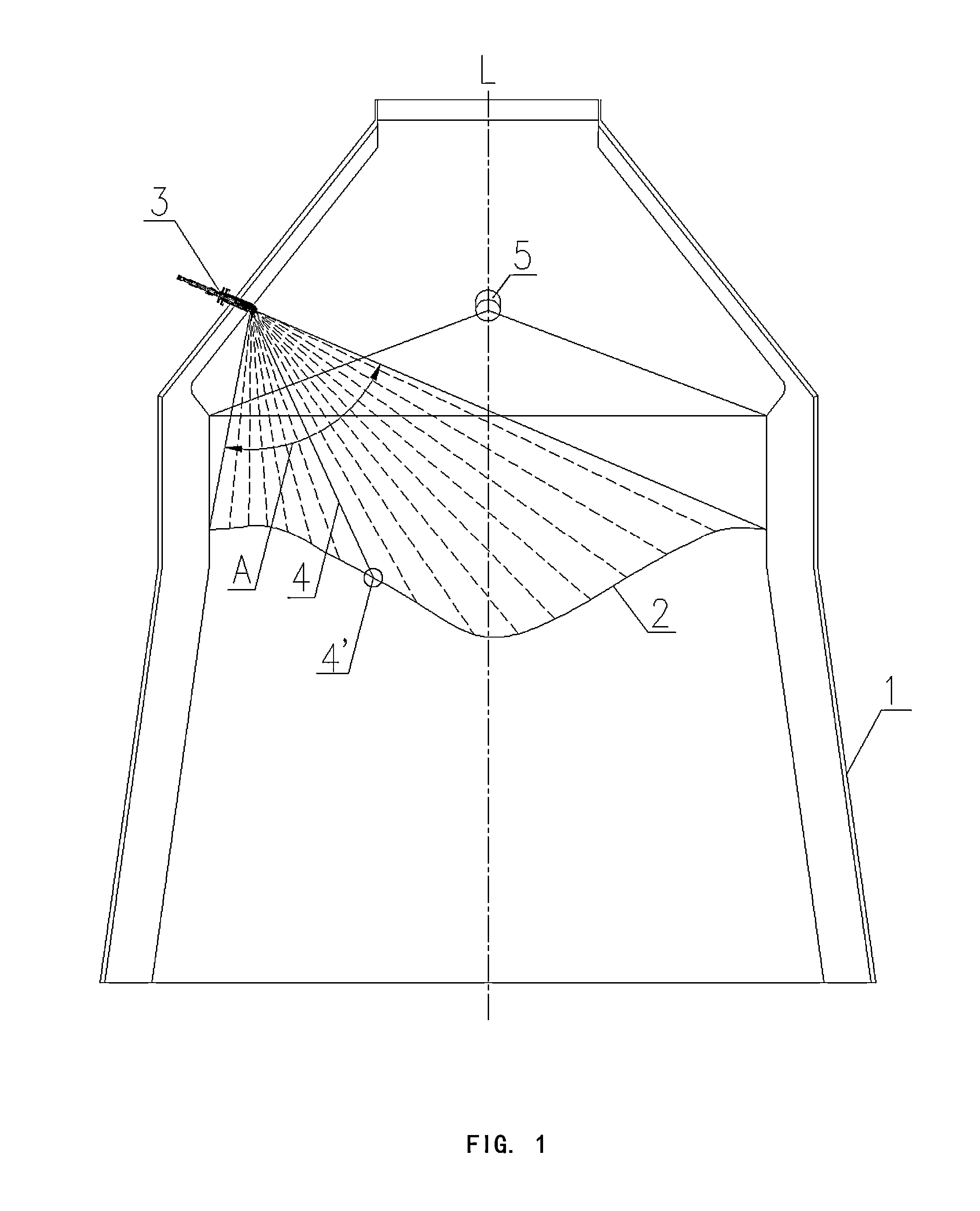
[0026]Referring to FIG. 1, a blast furnace 1 is generally in a central symmetrical shape around a central axis L, and a burden surface 2 of the charged burden is also usually in a substantially central symmetrical shape around the central axis L. In the cross-sectional view of FIG. 1, the central symmetry is represented as left-right symmetry around the axis L.

[0027]In the embodiment shown in FIG. 1, a system for on-line measuring burden surface in a blast furnace according to the present invention comprises a laser emitter 3 and a video camera 5 disposed above the burden surface 2. The laser emitter 3 and the video camera 5 can be positioned and / or disposed in the blast furnace 1 in a conventional manner, e.g., in a manner as stated in the Chinese Patent ZL200610089415.6.

[0028]The laser emitter 3 transmits one laser beam 4 which is “visible” for the video camera 5. Noticeably,...


PUM


Abstract

The present invention discloses a system and method for on-line measuring a burden surface in blast furnace to get burden surface information. The system comprises laser emitter(s) disposed above the burden surface and emitting laser beam(s) to continuously scan at least one portion of the burden surface; a video camera configured to shoot burden surface images, each of which comprises a detection point pattern formed by the laser beam incident on the burden surface; an image processing device configured to receive the burden surface images transferred from the video camera and output the burden surface information. As compared with the prior art, the present invention may substantially reduce the cost of the measuring system and obtain burden surface information sufficiently accurate with a large number of actual detection points. Furthermore, the system for on-line measuring a burden surface in blast furnace according to the present invention may use less number of laser emitter (even one laser emitter), so it is more advantageous to minimize the system and may simplify laser emitter protective measures.

Description

FIELD OF THE INVENTION[0001]The present invention generally relates to a field of measuring of blast furnaces, and particularly to a system and method for on-line measuring a burden surface in a blast furnace.BACKGROUND OF THE INVENTION[0002]A metallurgical blast furnace usually operates in a closed state, and has an in-furnace environment of such as high temperature, high pressure, high dust content and high humidity. Hence, operators can not directly observe in-furnace information, e.g., burden surface in the furnace, charging process and operation states of in-furnace devices, and he has to deduce the in-furnace information from values of conventional detecting meters detecting parameters such as temperature, pressure, flow rate and so on.[0003]In order to obtain the desired in-furnace information, infrared scanning and microwave scanning methods have been used to detect the interior of the blast furnace. However, these detections require applying complicated detecting and receiv...

Claims


Application Information

Patent Timeline
IPC IPC(8): C21B7/24H04N7/18
CPCC21B7/24H04N7/183F27B1/20F27B1/28F27D21/00F27D2021/0042
Inventor GAO, ZHENGKAIZHAO, CHENGPINGGAO, YONGGAO, TAIGAO, QIAN
Owner GAO ZHENGKAI
Why Eureka
Try Eureka